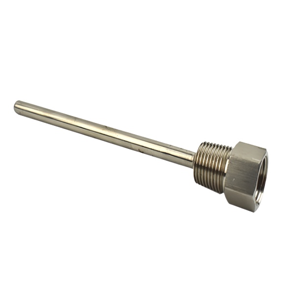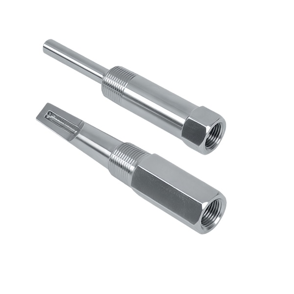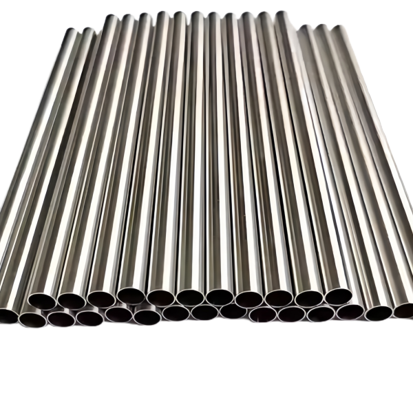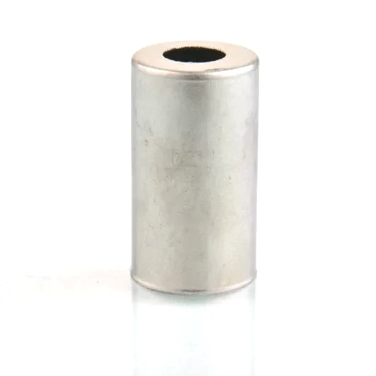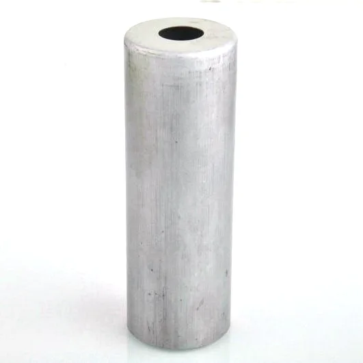
A double-tube housing with a welded flange base is a probe that carries two tubes, and the “double” is not a detail – it is either a redundancy, a differential measurement, or one tube for each of two purposes. Which one it is determines whether the two tubes have to be identical, whether they have to be at the same length, and whether the accuracy of the instrument depends on them being matched. On most of these designs the matching is not stated anywhere and it matters.
Forming, fixture welding, weld dressing and inspection, then surface treatment, at +/-0.03 mm on stepped bores with concentricity per print and capability checked on the first article. So the tight band is on the bores – and on a double-tube part the relationship between the two bores is where the interesting tolerance lives.
Why two tubes, because the answer changes the whole part
- Differential measurement. One tube carries a reference temperature and one carries the process temperature, and the instrument measures the difference. Here the two tubes’ lengths, materials and thermal characteristics directly determine the measurement, and a mismatch between them appears as an offset error.
- Redundancy. Two sensors so the installation survives one failing. Here the two must be interchangeable – same response, same accuracy class, same calibration basis – or the redundancy is an operational complication rather than a protection.
- One for sensing and one for a reference or an alarm point. Here the two may deliberately differ, and the requirement is that each matches its own function.
- Or purely structural – one tube is the process connection and one is the mounting.
So the first item on this part’s specification is: what do the two tubes do? Because in the differential case they must be matched, in the redundancy case they must be interchangeable, and in the mixed case they must not be. And the drawing will specify two bores and leave it at that unless somebody says.
The relationship between the two tubes
If the two tubes are matched – which is the case in one form or another on almost every double-tube probe – then the tolerances that matter are the relationships between them, and they are worth naming.
- Length, from the process face. On a differential probe, two tubes of different length give two different junctions in the temperature gradient, and the difference between them appears directly as an offset. So the length difference between the tubes should be a stated requirement with a tight band, referenced to the process-facing face – and it is not a dimensional tolerance of the part so much as a matching specification between two features.
- Diameter and wall. Two tubes of different wall thickness have different thermal conductivity along them and different response times, and on a differential measurement a response mismatch appears as a lag error during transients rather than as a static offset.
- Material. Two tubes in different alloys will have different conduction and possibly different corrosion in the same process, and on a differential measurement that is a systematic difference that will not average out.
- Concentricity of the two bores to each other and to the flange’s axis. If the two tubes are adjacent and share a flange, their relative position affects how the process fluid reaches them – one tube may see a better flow than the other, and on a differential measurement that is a systematic difference.
The flange, and what welding it to the tubes does to the alignment
A welded flange base means the tubes are joined to a flange in a fixture, and the flange is what positions both of them. That has three consequences.
- Each tube’s position is set by the weld fixture, and the weld’s shrinkage is part of that. So the position of each tube relative to the flange’s axis is a weld outcome and it will vary unless the fixture controls it – and where the two tubes have to match, a variation in one against the other is a variation in the matching.
- The weld’s heat is applied near where the tubes join, and on a thin-wall tube that heat distorts the tube. So the tube’s straightness and its roundness immediately above the weld are affected by the welding, and on a double-tube part both tubes are affected and they may be affected differently depending on their position in the fixture.
- And the flange’s own flatness is at risk from the welding – the weld’s shrinkage pulls on the flange, and a flange that is warped will not seal against its mating flange and will not locate. So on a welded flange the face’s flatness after welding is a process outcome and it may need a stress relief or a finish machining operation after the weld – and the sequence has to be on the routing.
The flange as a mounting interface
Because it is a flange, it carries all the same requirements as any flanged part, and on a probe they compound.
- Bolts, a bolt circle, and a face that stays flat under the bolts’ preload.
- Sealing, with a gasket or a face seal, and a stated flatness and finish.
- And the two tubes’ position relative to the flange’s bolt pattern, so the probe assembly can be installed in a vessel and the tubes will be where the design assumed. On a flange with tubes on one side and bolts on the other, the tubes’ position relative to the bolt circle is a drawing dimension that is usually missing.
- And the flange’s thermal mass. A flange is a significant mass of metal at the end of a probe, and it is at the cold end. So the flange’s thickness and diameter contribute to the probe’s conduction error, and on an accuracy-critical probe the flange is often the largest single source of it. A heavier flange is structurally better and thermally worse.
On a double-tube probe, tubes and flange need not share an alloy
Stock runs to carbon steel, 304 and 316 stainless steel, aluminium and brass, with special grades sourced when volumes justify. Three points specific to this part.
- The tubes and the flange can reasonably be different alloys, and on a double-tube probe they sometimes are – the process side needs corrosion resistance and the flange side needs to match the vessel. Where they differ, the junction is a weld between dissimilar alloys and the weld’s own metallurgy has to be compatible.
- 316L rather than 316 wherever there is heat input, and on this part the heat input is significant because there are two welds. The L grade matters more here than on a single-weld part.
- And on a differential probe the two tubes must be the same material. That is not a metallurgical preference – it is a measurement requirement, and it should be stated as one.
A welded flange is usually machined after finishing, so the face is bare
Natural, plated or coated per the print, with the agreed finish logged and travelling with the part number. Three items on a welded flange.
- The sealing face, unmasked and with a stated finish. It is the flange’s whole purpose and it is usually machined after the welding, which means it is machined flat despite the weld’s distortion – so the finish’s specification and the flatness’s specification have to be consistent.
- Any thread or spigot, unmasked or post-finish.
- And the process side of the tubes, where the finish is a corrosion requirement, and on a food or a pharmaceutical application it is a documented product-contact surface with its own passivation record.
Tolerance, and the one that is not a dimension
+/-0.03 mm on stepped bores with concentricity per print. The flagged dimensions are four, and the fourth is not a size.
- Each bore’s diameter and roundness, to its own fit.
- Each bore’s concentricity to the flange’s axis, as two separate relationships rather than one.
- Each bore’s length from the process face, and the difference between them as a stated matching requirement where they are matched.
- The sealing face’s flatness and perpendicularity to the flange’s axis, measured after the welding and after any finish machining.
- And the matching requirement itself – the difference in length, the difference in response, the difference in material – stated as a specification rather than implied. On a differential probe this is the specification that makes the instrument accurate, and it is the one that never appears on a dimensional drawing.
Two bores in one part have to be measured against each other
First articles and batch samples on the CMM, with capability checked on the first article. On a double-tube part the inspection plan has an item that a single-tube part does not.
- Each bore measured separately, on diameter, roundness, and concentricity to the flange.
- The relationship between the bores – the length difference, the position difference – measured as a pair, because that is what determines whether the instrument is accurate.
- A functional check where elements are fitted – a resistance or EMF check on each channel, and on a differential probe a comparison between them. Two channels that are individually within specification can still be mismatched by enough to produce a systematic error, and only the pair measurement finds it.
- The flange’s sealing face after the welding and after finishing, since that is when it is actually flat.
- And a leak test where the flange seals the process, because on a welded flange the leak path is the weld or the face and they fail differently.
Are the two tubes a matched pair, redundancy, or sensing and something else?
What do the two tubes do – are they a matched differential pair, interchangeable redundancy, or one sensing and one for something else? That is the first question because it decides whether the two tubes must be identical, and nothing else on the drawing matters if that is unresolved. And the second question is about the installation: how is this flange mounted, and how much of the probe’s error budget belongs to the flange itself? Because a flange is the heaviest, coolest part of a probe and it sits at the end of the temperature gradient, and on a long probe the flange’s own thermal mass can dominate the conduction error – so where the probe’s accuracy is tight, the flange’s dimensions are an accuracy specification and not just a mounting one. And there is a third question that is worth asking on a welded flange because it is rarely asked and it is discovered late: is the flange’s sealing face machined after the welding? If it is, the welding’s distortion has to be removed and the finish machining has to be in the sequence. If it is not, then the flange’s flatness as delivered is the welding’s outcome and it has to be held by the weld fixture rather than by the machine. Those are two different processes with two different costs, and the drawing does not say which one it is.
This part belongs to our Sensor Housings range. The sensor housings pages collect the process notes, common materials and inspection points behind every product in the family.
Specifications
| Item | Temperature Sensor Housing with Double-tube Welded Flange Base |
|---|---|
| Brand | AUNOV |
| Designing | Driven by your drawing or a physical sample – samples are reverse-measured into a controlled drawing; changes are priced before they are made. |
| Tooling | Tooling is built and held under your part number, so tooling lead time stays under our control, and the charge is refundable against agreed volumes. |
| Samples | Sample approval is documented: dimensions, finish and material recorded for later comparison. |
| Materials | Stock runs to carbon steel, 304 / 316 stainless steel, aluminium and brass; special grades are sourced to the drawing when volumes justify. |
| Surface finish | Natural, plated or coated – the print decides, and the agreed finish is logged; the agreed finish travels with the part number. |
| Processing | Forming, fixture welding, weld dressing and inspection, then surface treatment. |
| Equipment | Deep drawing presses plus CNC turning centres for machined faces; first articles and batch samples are checked on the CMM. |
| Tolerance | +/-0.03 mm on stepped bores, concentricity per print; capability is checked on the first article before the run continues. |
| Delivery terms | FOB, CIF or DDP per Incoterms 2020, payment by T/T, L/C at sight or D/P; each volume tier carries its own quoted price. |