
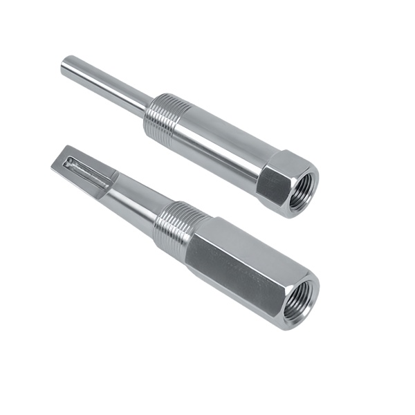
The Stainless Steel Long Thermowell with Slotted Tip is a deep-reach thermowell whose sensing end carries one or more slots cut into the tip rather than being a plain closed tube. The slots are there to change how the tip behaves: they reduce the metal mass at the sensing end so the sensor responds faster, they let process fluid reach the sensor more directly, and in some designs they let the tip flex or spring to make contact. But a slotted tip is also the most vulnerable part of the well – the slots cut into the pressure boundary and into the thinnest, most worked metal at the end of a long, slender part. This page covers why the tip is slotted, how the slots are cut and how strength and response are balanced.
Slots trade response time against strength, deliberately
A solid thermowell tip is strong but slow: it has to be heated all the way through before the sensor inside sees the full process temperature, and its wall insulates the sensor from the flow. Cutting slots into the tip removes metal from the sensing end, which lets the flow reach the sensor sooner and reduces the thermal mass that has to be heated, so the probe responds faster. The trade is that those same slots remove material from the pressure boundary and from the already-thin end of a long well, so the tip is weaker and more prone to damage than a solid one.
- Slot depth and pattern are set against the response-time target, but capped by the pressure and strength the tip still has to hold.
- The remaining metal between and around the slots is what carries the load, so slot geometry is a strength calculation as much as a thermal one.
- Where the well sees high pressure or erosion, we discuss whether a slotted tip is appropriate at all, because the slots concentrate stress in the highest-risk region.
Cutting slots into a long, slender, closed tip
The slots are cut after the well is drawn and closed, into the formed tip, and doing that on a long slender stainless steel part is awkward: the part wants to flex under the cutting force, the tip is the hardest-worked and least ductile metal in the well, and a slot cut with the wrong clearance or a dull tool leaves a burr or a torn edge that becomes a crack site. The slotting is a controlled secondary operation with the well supported, not an afterthought.
- The well is supported along its length during slotting, because a long slender part deflects under the cutting force and the slot wanders.
- Slot edges are cut clean and deburred, since a torn or burred slot edge on a stainless steel tip is a stress riser that cracks under thermal cycling.
- Where the tip metal is work-hardened from the draw, we discuss an anneal before slotting so the slots cut cleanly and the edges stay sound.
Straightness over a long well is still the hidden specification
Adding slots to the tip does not change the fact that this is a long thermowell, and a long thermowell’s hardest requirement is straightness over its full length. The well has to slide into a deep port or guide without binding, and it has to keep its slotted sensing tip centred in the flow. The slotting operation, which cuts into one end of a long part, is one more thing that can disturb that straightness, so straightness is re-verified after slotting rather than assumed to carry over from the drawn tube.
- Straightness is measured over the full length after slotting, on rollers or in v-blocks, because the slotting can add a bow.
- The well is supported through slotting, handling and packing, since a long slender part bends if it is not held along its length.
- Where the well reaches into a close-clearance port, the combined straightness is checked against that clearance, not just a general tolerance.
Sensor seating inside a slotted tip
The whole point of the slots is to get heat to the sensor faster, and that only works if the sensor actually seats against the inside of the slotted region rather than sitting in an air gap behind solid wall. The internal bore through the slotted tip therefore has to be finished and sized so the sensor contacts the metal, and the sensor has to be positioned so its sensing point lines up with the slotted, flow-exposed region. A slotted tip with a sensor seated behind solid wall is a slow tip with a weaker pressure boundary – the worst of both.
- Internal bore finish through the slotted region is controlled so the sensor seats against metal, not an air gap.
- Sensor seating depth is verified so the sensing point aligns with the slotted, flow-exposed part of the tip.
- Wall thickness between the slots and the bore is checked, because that remaining web is what both carries pressure and conducts heat to the sensor.
How we verify a long thermowell with a slotted tip
Verification checks the slots, the strength of what is left and the straightness of the whole well, because a slotted long tip fails at whichever of the three is weakest.
- Slot geometry: slot width, depth, pattern and count verified to the drawing, against the response-time target they were designed for.
- Slot edges: inspected for burr, tearing or fine cracks, with the edge condition confirmed sound on stainless steel that may have been work-hardened by the draw.
- Remaining strength: wall thickness between slots and bore measured, confirming the web still holds the design pressure.
- Straightness: measured over the full well length after slotting, on rollers or v-blocks, against the tolerance the port clearance needs.
- Sensor seating: bore finish and seating depth verified so the sensor contacts the slotted region.
- Material, passivation and fit check: stainless steel grade and passivation confirmed per lot, and the well inserted into its guide with the sensor seated before the run.
First articles and retention samples are kept for the programme, so a repeat run of the slotted-tip well is drawn, slotted and trued to the same verified baseline. On a long part whose slots buy response time at the cost of strength at its most fragile end, that baseline is what keeps a second batch responding quickly and still holding pressure.
Sensor Housings is the range this part sits under; the overview page pulls together the tooling logic, finishing options and tolerance notes that apply across the family.
Specifications
| Item | Stainless Steel Long Thermowell with Slotted Tip |
|---|---|
| Brand | AUNOV |
| Designing | Send drawings, or send a sample to be measured, DFM feedback is returned with the quote. |
| Tooling | Every die designed and built in our toolroom, each die held against your part number. |
| Samples | Approval samples of the thermowell ship with a dimensional report and material certification. |
| Materials | Stock for this part leads with 304 / 316 stainless steel, alongside carbon steel (SPCC / DC01), aluminium, brass and copper, per the drawing. |
| Surface finish | Plating, e-coat, powder coating, anodising or passivation, selected against the drawing requirement. |
| Processing | Staged deep drawing, with in-line annealing where the draw ratio requires, pierced and finish-machined on the same floor. |
| Equipment | Our press floor runs 5-250 T mechanical and 250-500 T hydraulic presses, CNC cells plus a temperature-controlled CMM room. |
| Tolerance | Tolerances to +/-0.1 mm as drawn, machined features held to +/-0.03 mm. |
| Delivery terms | FOB is standard; DDP offered for EU and US, T/T and L/C accepted, D/P for established customers, call-off scheduling supported. |
Related Products



Frequently Asked Questions
Why slot the tip?
Slots cut metal mass at the sensing end so the sensor responds faster, let process fluid reach it more directly, and in some designs let the tip spring to make contact.
What is the trade-off of slots?
They remove material from the pressure boundary and the already-thin end of a long well, so the tip is weaker and more prone to damage than a solid one.
How are the slots cut?
By a controlled operation sized to the wall so the slots open the flow path without undermining the pressure boundary.
Which grade for a long well?
304 or 316 stainless steel, with the wall and slot depth set against the process pressure and the reach length.
Request a Quote for This Part
Send a drawing or sketch — get material advice, tooling cost and a per-piece price within 24 hours (working days).