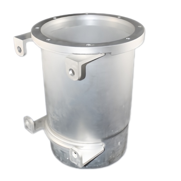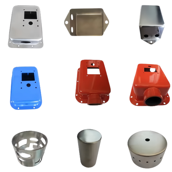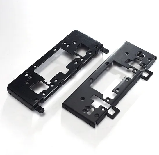
Black stamped frame brackets with cutouts: the cutout is the feature, and it is a weakening
Black stamped frame brackets with cutouts exist to save material, to clear something, to reduce weight, or to let something pass through – and each of those reasons is a way of removing exactly the material that was carrying the load. A cutout in a structural bracket is therefore a tension between two requirements, and the whole design question is where the cutout can be without taking away the bracket’s ability to do its job.
We stamp and form in a progressive die with minimal secondary work, on 5-250 T mechanical presses with progressive dies, with in-house toolmaking keeping dies and fixtures maintained. Batch records are filed so a repeat order starts from approved data. Pierced holes to +/-0.03 mm and formed sections to +/-0.1 mm, with GD&T per drawing and PPAP-style reports on request. T2 copper strip is held for conductive parts, with brass or nickel under-plating where solderability is specified, and finish is selected from the drawing – plating, coating, anodising or passivation – with alternatives quoted with the quotation and samples approved in writing. This page is about cutouts, the stress they create, and the four rules that decide where they can go.
What a cutout does to a bracket’s strength
A cutout removes material and it changes the load path. Four distinct effects, in descending order of importance on a stamped bracket:
- It reduces the section where the load runs. A bracket that carries load across a face with a cutout in that face has been weakened by exactly the cutout’s width at the load’s line. This is the crudest effect and the easiest to calculate – the section’s net width is what carries the load.
- It moves the neutral axis and the shear centre. Where the cutout is off-centre, it makes the section asymmetric, and an asymmetric section twists under an off-axis load. On a bracket this can be worse than the section reduction suggests, because the part now behaves like a channel rather than a flat plate.
- It creates a stress concentration at its edge. The corner of a cutout is where the stress is highest – both because the material is interrupted and because the corner is where two free edges meet. A square corner in a cutout is a genuine stress riser; a radiused corner is not.
- It changes the part’s behaviour under fatigue. A cutout’s corner is a crack initiation site under cyclic loading, and a crack will grow from there. On a bracket that sees vibration, a cutout’s corner radius is a fatigue life parameter and not a cosmetic detail.
The four rules that decide where a cutout can go
| Never in the load path without a check | If the bracket’s load crosses the cutout, the net section has to be adequate and the deflection has to be recalculated. A cutout to save material in a high-stress region often costs more in deflection than it saves in material – the material saved was not the expensive part. |
|---|---|
| Radiused corners, always | A radiused corner reduces the stress concentration substantially compared with a square one, and on a stamped part the radius is a forming feature rather than a machining one, so it is cheap. There is no reason to specify a square corner on a cutout in a structural bracket. |
| Keep away from bends and welds | A cutout close to a bend is a cutout in a region that is already the most stressed part of a formed bracket, and a cutout close to a weld is in the region of the weld’s own heat-affected zone. Both are poor locations and there is usually a better one. |
| Keep the material around it continuous | A cutout that nearly reaches an edge leaves a thin ligament, and a thin ligament is a stress concentration and a weak section. Where a cutout must be near an edge, the remaining ligament has to be dimensioned and its failure load considered. |
Cutouts as lightening, and the cheaper way
Where a cutout exists purely to reduce weight or to save material, it is worth asking whether a formed feature would do the same job more cheaply. The alternative to a cutout for stiffness is a formed bead or a rib, and the comparison is genuinely close:
- A cutout removes material and reduces weight, and reduces the section’s stiffness and strength as a consequence.
- A bead or rib adds stiffness with a small amount of material, and it increases the section’s moment of inertia – which is what actually governs bending stiffness. For a given mass, a ribbed section is much stiffer than a plain one.
So a bracket that needs to be lighter but also needs to be stiff is usually better served by a bead than by a cutout. A cutout is right where material must genuinely be removed – where something has to pass through, where a fastener needs access, or where weight is critical and the load is low. It is the wrong tool where the bracket is highly loaded and the saving is modest.
Black finish, and the two things it changes
On a black coated bracket with cutouts, two finishing effects are worth stating:
- The coating does not reach inside a narrow cutout. A cutout with a width much smaller than the spray’s access will have a thinner coating on its internal walls than on the face, and a cutout in a severe environment is a crevice – which is where coating failure and corrosion start. Zinc flake systems are markedly better in crevices than conventional plating, and a wider cutout is better than a narrower one for this reason.
- The cutout’s edge is where the coating is thinnest and where burrs are. A sheared or pierced cutout has a sheared edge, and on a visible black part the edge will show the coating thinning. If the bracket is visible, the cutout’s edge condition and its coating need to be specified together – and on a visible part a small break or radius on the cutout’s edge is worth doing because it removes both the burr and the coating’s thin spot.
Material, and the copper note
T2 copper strip is held for conductive parts, with brass or nickel under-plating where solderability is specified. On this part family that note applies to the subset of brackets that conduct – an earth strap, a busbar support, a shielding bracket, a part that carries current – and the requirements there are different:
- Conductivity is the design number, and a bracket that is part of an electrical path has to be specified for its resistance, not just for its geometry.
- Solderability requires a surface condition. Copper solders readily if it is clean; if it will be soldered, brass or nickel under-plating is specified because it gives a solderable surface and because the plating protects the copper from oxidation. That is a functional plating specification rather than a decorative one.
- Carbon steel, 304 and 316 stainless steel for structural and non-conductive brackets, and 316 for a corrosive environment. Copper is not a structural material in this context and is used only where its conductivity or its solderability is the point.
- Aluminium where mass matters, with the usual stiffness penalty of a third of steel’s modulus.
On a cutout bracket, the pierced holes take the tight band
Pierced holes to +/-0.03 mm and formed sections to +/-0.1 mm is the stated structure, and on a bracket with cutouts it maps as follows:
- The pierced holes take the tight band, and they are the holes that locate the bracket or receive a fastener. They should be located as true position to a datum, and they should be pierced in the flat where the sequence allows.
- The cutouts take the formed-section band, which is appropriate – a cutout’s size is not usually a functional requirement, its position relative to the load path is.
- Cutout position relative to the bracket’s features is a functional dimension, even if the cutout’s own size is not. Where a cutout has to clear something, that something’s tolerance and the cutout’s tolerance have to be stated together.
- Corner radii on every cutout are functional under cyclic loading and should be specified rather than left to the piercing tool.
Cutouts are usually added, and they weaken
Seven things, and the first two are what determine whether the cutouts are acceptable at all:
- What the cutouts are for – clearance, access, weight, or lightening. Each has a different constraint and a cutout with no stated purpose cannot be reviewed.
- Whether any cutout crosses the load path, and if so the net section and the resulting deflection.
- Corner radius on every cutout, as a specified dimension.
- Edge distance from each cutout to the bracket’s edges and bends, so the remaining ligament is dimensioned.
- Cutout positions relative to the bracket’s locating features, as true position where they matter.
- Whether the load is cyclic, because on a vibratory application the cutouts’ corner radii are the fatigue life.
- The finish, and whether it is masked anywhere – and on a part with a black coating, whether the cutouts’ internal walls are acceptable at the coating’s coverage.
Does each cutout need to exist?
Does each cutout need to exist? On a bracket family, cutouts are very often added early because a lighter part feels like a better part, and they accumulate – each one individually reasonable, and collectively a bracket that is now weaker, heavier in terms of manufacturing complexity, and more expensive than the bead that would have achieved the same result. Reviewing the cutouts as a set, rather than accepting them one at a time, is worth doing at the design stage: a cutout removed in design costs nothing, and a cutout removed after a fatigue failure costs a great deal.
This part belongs to our Custom Metal Stamping Parts range. The custom metal stamping parts pages collect the process notes, common materials and inspection points behind every product in the family.
Specifications
| Item | Deep Drawn Copper Oxygen Chamber |
|---|---|
| Brand | AUNOV |
| Designing | Made to your 2D/3D drawings (PDF, DWG, STEP, IGS) – samples are reverse-measured into a controlled drawing; changes are priced before they are made. |
| Tooling | Dies, fixtures and gauges are made in our own toolroom, so tooling lead time stays under our control, and ownership is confirmed on the quotation. |
| Samples | Samples are produced on the production tooling, so what you approve is what you get. |
| Materials | T2 copper strip for conductive parts, with brass or nickel under-plating where solderability is specified. |
| Surface finish | Finish selected from the drawing: plating, coating, anodising or passivation; alternatives quoted with the quotation, samples approved in writing. |
| Processing | Stamping and forming in a progressive die with minimal secondary work; batch records are filed so a repeat order starts from approved data. |
| Equipment | Mechanical presses 5-250 T with progressive dies, with in-house toolmaking to keep dies and fixtures maintained. |
| Tolerance | +/-0.03 mm on pierced holes, +/-0.1 mm on formed sections; GD&T per drawing, PPAP-style reports on request. |
| Delivery terms | CIF or DDP, with FOB available, T/T with deposit and L/C for larger runs; repeat orders reuse the approved first article. |