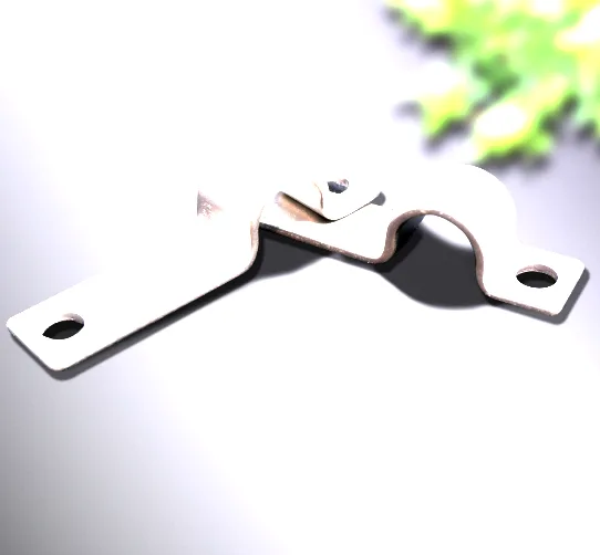
A tab bracket lives or dies on one bend radius
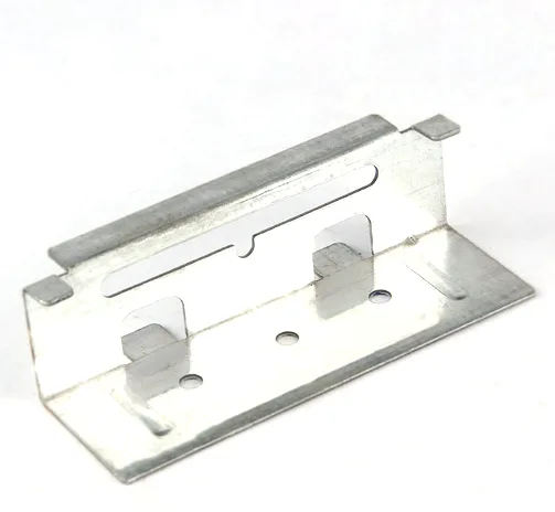
A custom stamped steel tab bracket is small, cheap, and often the part that determines whether a product works. It connects something to something else – a wire to a panel, a component to a chassis, a hinge to a body – and it usually does so through a small tab that is bent to develop a retention force or a locating feature. That single bend is where the design lives or dies, and almost everything that goes wrong with a tab bracket goes wrong there.
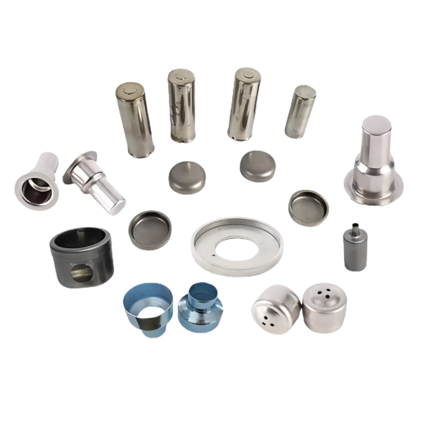
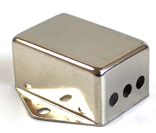
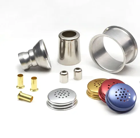
We coil-feed stamp these, deburred and finished to the print, with in-process checks between stages, on 5-250 T mechanical presses with dedicated dies and in-house toolmaking keeping dies and fixtures maintained. Pierced holes are held to +/-0.03 mm and formed sections to +/-0.1 mm, and capability is checked on the first article before the run continues. Standard stock is carbon steel in SPCC and DC01 grades, 304 and 316 stainless steel, aluminium and brass, with mill certificates and heat numbers accompanying the first article. Plating, powder coating, anodising or polishing per the print, with masking and laser marking available where needed. This page is about the tab, the bend it depends on, and the decisions that make it repeatable.
What the tab is for, and the four common jobs
The word “tab” covers four different functional things, and the drawing for each is different:
| A locating tab | Fits into a slot or a hole and defines the part’s position. The requirement is the tab’s width, its thickness, and its angular position relative to the main body. No force involved – this is a geometric feature. |
|---|---|
| A retention tab | Springs against an edge to hold the part on, or snaps into a hole to stop it coming off. The requirement is a retention force, and the tab’s material condition matters as much as its geometry. |
| A weld or solder tab | A flat extension for attaching the part to something else. The requirement is flatness and a clean surface, and it drives the whole stamping sequence because the tab must stay flat while the rest of the part is bent. |
| An earth or bonding tab | A flat, plated, defined-surface area for a wire or a busbar. The requirement is a surface condition and a contact resistance, and it needs masking logic on the finish. |
A drawing that says “tab” without saying which of these it is has not specified enough, because the tolerance on the tab’s angle will be a general tolerance for one kind and a controlled value for another.
The bend: radius, springback and thickness
The bend that forms the tab is where the part’s behaviour is determined. Four things, in order of importance:
- The inside bend radius. Too tight and the outer fibre of the bend cracks – the risk rises sharply with material strength and with thickness. Too generous and the tab’s angle is less controlled and the part’s footprint grows. The standard guidance is that the inside radius should be at least one material thickness, and two to three thicknesses gives a much more stable bend and better fatigue life.
- Springback. The tab returns toward flat by an amount that depends on the material’s yield strength, the bend radius and the thickness. It is predictable, and it is compensated in the tooling by over-bending. What it is not is eliminated – which is why the tab’s angle needs a tolerance and why the material specification matters.
- Thickness tolerance. A tab’s angle is sensitive to thickness. A coil running at its thick edge produces a different tab angle from the same coil at its thin edge. If the tab’s angle is a controlled feature, the incoming material’s thickness band has to be known and the die compensated for the middle of it.
- Rolling direction. Bending transverse to the grain is harder and less stable than bending along it. On a part with a tab, the grain direction relative to the bend is a real drawing requirement and it is worth stating as rolling direction rather than leaving it to the producer.
Keeping the part flat while bending it
A tab bracket is usually a flat blank with one or two bends, and the sequencing problem is real: the tab has to stay flat while the rest of the part is formed, or it has to be formed last. Three approaches:
- Form the tab last. The tab’s bend is the final operation, which keeps it free from the distortion caused by earlier bends. The simplest and most common approach, and the one to prefer.
- Form the tab first, with relief. If the tab must be formed early, a relief cut or a bend-relief slot between the tab and the adjacent bend prevents the material from being in tension at the corner. This is the standard fix for a corner that would otherwise crack or distort.
- Emboss or bead the surrounding area. A local bead near the bend constrains springback and holds the tab’s angle, and it can substitute for a tighter die.
Holes at +/-0.03 mm: usually a wire, a rivet, or a locating pin
The tight band on this part is on the pierced holes, and that tells you what the holes are for. At that tolerance they are functional:
- A wire or lead termination hole. A small hole for a wire to pass through or to be crimped into. Its position relative to the tab and to the mounting hole is what determines whether the assembly works.
- A locating hole. A pin or dowel that sets the part’s position. This is a true position control and it needs a named datum.
- A fastening hole that receives a rivet or a self-tapping screw. Here the hole size sets the fastener’s fit and its position sets the clamp.
Three practical points. A hole at +/-0.03 mm should be pierced in the flat, where the tooling is rigid – not formed after bending. Its position should be called out as true position to a datum rather than as a chain of coordinates. And if the hole carries a fastener, the head’s bearing area needs to be flat, which on a stamped part means the local surface must not dish.
Materials, and the grade that changes the bend
Carbon steel in SPCC and DC01 grades, 304 and 316 stainless steel, aluminium and brass, with mill certificates and heat numbers accompanying the first article. On a tab bracket, the material choice is largely a bendability and a force question:
- SPCC and DC01 carbon steel. The general case. Ductile, forgiving in the die, and the material’s temper matters if the tab is a spring.
- Stainless Steel 304 or 316. Drawn at higher tonnage, springs back more, and is substantially harder to form – so the bend radius needs to be more generous and the tooling needs to be specified for it. Worth it where the part sees moisture or corrosion.
- Aluminium. Forms easily and springs back differently. If the tab is a retention feature, aluminium’s lower yield strength means it will not hold as much force, and the tab may need to be wider or thicker to achieve the same retention.
- Brass. Forms well and is used where conductivity or a specific corrosion behaviour applies.
If the tab is a spring element, the grade and temper should be confirmed in writing and the retention force stated on the drawing. Otherwise the part is specified as a shape rather than as a function, and a repeat order will not necessarily behave like the first batch.
Finish, masking and the tab
Plating, powder coating, anodising or polishing per the print, with masking and laser marking available where needed. Three finishing points specific to this part:
- A coating on the tab changes its force. A plated or coated tab is thicker and stiffer than a bare one, so the retention force changes. Where the tab is a spring, either the finish has to be excluded from it or the force specification has to account for the coating.
- A coated tab wears differently. A plated contact point wears at a different rate than bare steel and can mark the mating part. Where the part is visible or where marking matters, this needs specifying.
- An earth or bonding tab must be masked carefully – its contact surface has to be a defined, clean, plated area. Masking logic on a small part is a real operation and belongs on the drawing.
Getting the tab bracket right
Quotation follows the print, not a catalogue, with DFM notes returned before any tooling is cut and the same drawing used for every repeat order. The die is dedicated to your part and maintained on a recorded schedule. Sample parts are measured and reported before submission, the approved first article becomes the gauge reference, and the signed sample is kept for future reorders.
Six things that make a tab bracket repeatable:
- Which kind of tab it is – locating, retention, weld, or earth – since each needs a different specification.
- The tab’s angle tolerance stated separately from the formed-section tolerance, because it is controlled by springback and material.
- Inside bend radius specified, and the material’s grade and temper confirmed.
- Rolling direction stated relative to the bend, if the tab is a controlled feature.
- Holes located as true position to a named datum, and pierced in the flat.
- The retention force, if the tab is a spring, and whether it applies before or after finishing.
And one question worth asking at review: does the tab need to be bent at all. A part with the tab formed in a separate assembly step, or a straight tab that is bent by the customer during installation, is often cheaper to make and far more tolerant of variation in the incoming material. It is worth having that conversation before the die is cut rather than after.
Custom Metal Stamping Parts is the parent range for parts like this one; the overview page gathers the tooling logic, finishing options and tolerance notes that apply across the family.
Specifications
| Item | Custom Stamped Steel Tab Bracket |
|---|---|
| Brand | AUNOV |
| Designing | Quotation follows the print, not a catalogue – DFM notes are returned before any tooling is cut; the same drawing is used for every repeat order. |
| Tooling | The die is dedicated to your part and maintained on a recorded schedule. |
| Samples | Sample parts are measured and reported before submission, so the approved first article becomes the gauge reference, and the signed sample is kept for future reorders. |
| Materials | Standard stock: carbon steel (SPCC / DC01), 304 / 316 stainless steel, aluminium, brass; mill certificates and heat numbers accompany the first article. |
| Surface finish | Plating, powder coating, anodising or polishing, per the print; masking and laser marking available where needed. |
| Processing | Coil-fed stamping, deburred and finished to the print; in-process checks sit between stages, not only at the end. |
| Equipment | Press shop with 5-250 T mechanical presses and dedicated dies, with in-house toolmaking to keep dies and fixtures maintained. |
| Tolerance | +/-0.03 mm on pierced holes, +/-0.1 mm on formed sections; capability is checked on the first article before the run continues. |
| Delivery terms | Order ships FOB unless you prefer DDP; payment by T/T or L/C, freight quoted to destination. |