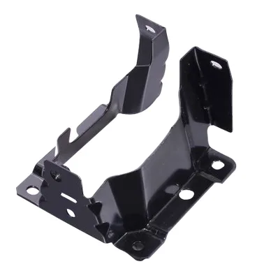
An automotive bracket assembly is a system that will be installed in the dark, in the rain, once
A black stamped automotive bracket assembly differs from a single stamped bracket in one way that changes everything: it is not a part, it is a set of parts that someone has to install correctly, in a dark and wet environment, with ordinary hand tools, once. That fact – the assembly, not the metal – is what should drive the specification, and it is the aspect that a per-part drawing tends to leave out. Three or four individually correct brackets, specified only as brackets, will still produce an assembly that is hard to install, easy to install wrongly, and impossible to inspect afterwards.
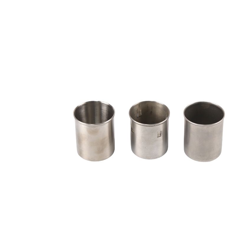
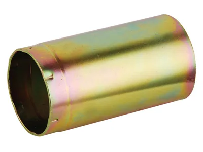
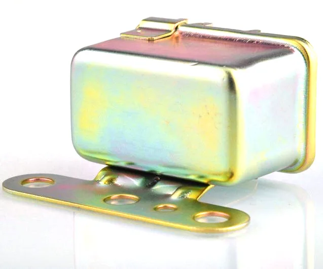
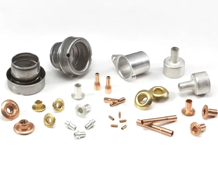
We coil-feed stamp these, deburred and finished to the print, with in-process checks between stages, on 5-250 T presses running progressive and compound dies, with first articles and batch samples checked on the CMM. Tolerance runs +/-0.05 mm to +/-0.1 mm across the part, with GD&T per drawing and PPAP-style reports on request. Stock covers carbon steel in SPCC and DC01 grades, 304 and 316 stainless steel, aluminium and brass, with special grades sourced to the drawing when volumes justify. Plating, coating or polishing to suit the drawing, with alternatives quoted with the quotation and samples approved in writing. This page is about specifying an assembly rather than a part, which is the main thing that makes this product different.
Three requirements an assembly has that a part does not
- Identifiability. Someone has to be able to tell which part goes where, in a box or a boot full of similar-looking black brackets. A single part does not need this; an assembly absolutely does. The usual solutions are a part number stamped or laser marked on the part, a distinguishable size or shape between otherwise similar brackets, or different finishes – and each has a cost that should be a conscious decision rather than an omission.
- An installation order. An assembly has a sequence, and in a confined space under a vehicle the sequence is often not obvious. Where the order matters – where one bracket has to go in before another can be reached – that has to be documented, and in some cases the geometry has to enforce it.
- A defined installed state. Each part’s dimension is only half the requirement; what matters is the assembled result. The assembly’s critical dimensions – a gap, an alignment, a clearance – are properties of several parts together and of how they are fastened. Those are assembly requirements and they belong on an assembly drawing, not derivable from four part drawings.
The environment is the real specification
An automotive bracket sees salt, water, mud, stone impact, and thermal cycling, and the coating is the whole defence. Four requirements that follow, and all of them should be on the drawing:
- Coating system with a thickness, because on a black part the film thickness also controls the appearance and the dimensional growth. Electrocoating at 15-25 microns is dimensionally well behaved and gives excellent uniform coverage; powder at 60-120 microns is tougher and looks better but changes every dimension it touches. Neither is wrong, and the choice has to be made with both in mind.
- Coverage of the crevices. Every folded joint, every bolt hole and every return on an automotive bracket is a place where a sprayed coating stops and bare steel starts. In a salt environment those are where corrosion begins. Zinc flake and zinc-aluminium systems are markedly better in a crevice than conventional electroplating, and reducing the number of folded joints is better than choosing a better coating.
- Stone impact. A thin electrocoat is more vulnerable to stone chipping than a thick powder coat or a zinc flake system, and this shows up as rust bloom at the chip sites within a year or two. On an underbody or wheel-arch bracket this is a real design consideration.
- The contact faces. Any surface where a bracket grips, seals, or electrically bonds must be masked or specified. A coating on a bonding surface changes the electrical resistance, and a coating on a gripping surface changes the friction.
Stamped features that serve installation
On an automotive bracket, three features exist purely for the installer and they are frequently left off the drawing:
- Location features that tolerate build variation. A slot instead of a round hole allows positional variation and is often the correct choice – and it must be stated as a slot with its width and length, not as a hole with a generous tolerance. A slot also stops the fastener from rotating under tightening, which on a bolted bracket is genuinely useful.
- Captive features. A flange that retains the fastener so it cannot be lost, or a lip that holds a fastener during alignment. On an assembly fitted in the dark these features are worth more than they cost.
- Hand access and clearance. Whether a socket and wrench can physically reach the fastener, and whether the bracket can be held in position while the fastener is started. This is only knowable from the assembly and it is the single most common reason an automotive bracket is returned: it cannot be fitted with the tool the technician has.
Tolerance structure across the assembly
The tolerance of +/-0.05 mm to +/-0.1 mm across the part is reasonable for individual brackets. The assembly-level requirements are what need thought:
- Which assembly dimensions are critical? A gap, a clearance, an alignment between two brackets, a symmetry. These should be called out at the assembly level with their own tolerances, and each one’s tolerance chain runs through several parts plus the fastener clearances.
- Where the chain is tightest. Usually at a bolted joint, where the fastener’s clearance and the bracket’s hole position add. A hole at tolerance on a bracket bolted to a hole at tolerance in a vehicle body may simply not line up – which is where a slot or a larger clearance hole is the correct design answer rather than a tighter tolerance.
- Fastener specification. The fastener’s clearance, its grade and its coating affect the assembly’s dimensions and its galvanic behaviour. A zinc-plated bolt with an aluminium bracket is a galvanic couple that will corrode; specifying both together prevents it.
Materials, and the galvanic question
Stock covers carbon steel in SPCC and DC01 grades, 304 and 316 stainless steel, aluminium and brass, with special grades sourced to the drawing when volumes justify. On an automotive assembly the material choice is a system decision:
- Carbon steel in SPCC or DC01 is the standard for a coated bracket, and it is the right answer for most underbody and interior brackets. It is cheap, it forms well, and the coating carries the corrosion protection.
- Aluminium for a bracket where weight matters – which on an automotive assembly means anywhere it is not load-bearing and not a ground path. Its modulus is a third of steel’s, so it needs deeper sections, and it needs galvanic isolation from steel fasteners.
- 304 or 316 stainless steel for a visible or exposed bracket, or where a ground or bonding requirement exists. Note that 304 in a hidden cavity is often chosen when it would survive perfectly well in coated steel, which is an expensive answer to a problem that does not exist.
- Brass is rare in an automotive bracket except where conductivity or a specific fastener requirement drives it.
The galvanic point deserves stating on the drawing: where dissimilar metals meet in the presence of moisture, the less noble one corrodes. An aluminium bracket with steel bolts and no isolation will corrode at the interface. A stainless steel bracket with zinc-plated fasteners has the same issue in reverse. This is a design requirement, not a detail.
An assembly needs an assembly drawing, not a set of part drawings
For an assembly product, the useful deliverable is more than a set of part drawings. Eight things, in descending order of value:
- An assembly drawing showing all the brackets, their installed positions, and the assembly’s critical dimensions with tolerances. This is the document that makes the product an assembly rather than a pile of parts.
- An installation sequence, or a note that the geometry enforces the order.
- Part identification on each part – stamped, laser marked, or made distinguishable by design.
- The fastener specification, including its clearance, its grade, its coating, and any isolation requirement at dissimilar metal interfaces.
- Tool access confirmed against the actual installation environment.
- The coating system per part, with thickness and masked areas, and any galvanic compatibility stated across parts.
- Which dimensions are assembly-critical rather than part-critical, and the tolerance chain that reaches them.
- Material per part, confirmed in writing, with the reason – because “aluminium for weight” and “aluminium because it was available” lead to very different brackets.
The habit worth building in
For any multi-part assembly, the practice that saves the most trouble is to install the assembly once, yourself, in the conditions it will actually be installed in – and to time it. A bracket set that takes twenty minutes to fit in a dry, lit workshop can take two hours in the rain under a vehicle, and that difference is the difference between a product people accept and a product people return. Nothing in a dimensional report will tell you that, and it is cheap to find out before the parts are in volume production.
This part belongs to our Custom Metal Stamping Parts range. The custom metal stamping parts pages collect the process notes, common materials and inspection points behind every product in the family.
Specifications
| Item | Deep Drawn Stainless Steel Stamping Deep Drawing Aluminum |
|---|---|
| Brand | AUNOV |
| Designing | Quotation follows the print, not a catalogue – a manufacturability review comes back with the quotation; changes are priced before they are made. |
| Tooling | Tooling is built and held under your part number, so the die charge appears as its own quotation line, and the die remains dedicated to your part. |
| Samples | Prototype and pre-production samples are provided against the drawing, so any deviation is corrected at sample stage, and later batches are gauged back to the signed sample. |
| Materials | Stock covers carbon steel (SPCC / DC01), 304 / 316 stainless steel, aluminium and brass; special grades are sourced to the drawing when volumes justify. |
| Surface finish | Plating, coating or polishing to suit the drawing; alternatives quoted with the quotation, samples approved in writing. |
| Processing | Coil-fed stamping, deburred and finished to the print; in-process checks sit between stages, not only at the end. |
| Equipment | 5-250 T presses running progressive and compound dies; first articles and batch samples are checked on the CMM. |
| Tolerance | +/-0.05 mm to +/-0.1 mm across the part; GD&T per drawing, PPAP-style reports on request. |
| Delivery terms | FOB, CIF or DDP per Incoterms 2020, T/T or L/C, with D/P accepted on repeat business; repeat orders reuse the approved first article. |