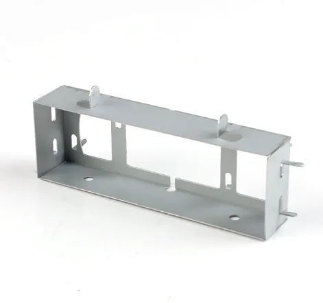
A frame channel bracket is a structural extrusion, and it is judged by its torsional stiffness
A galvanized stamped frame channel bracket is a channel section used as a structural member – part of a frame, a rail, a support. Once a channel is carrying load as a structural member rather than holding something to a surface, the section’s geometry stops being a shape and becomes a structural property. The one that catches people out is torsion: a channel is very good in bending and very bad in twisting, and in a frame the twisting is often the governing condition even when the loads look purely vertical.
We stamp and form in a progressive die with minimal secondary work, on a press shop with 5-250 T mechanical presses and dedicated dies, with secondary operations on CNC turning centres and CMM inspection. Batch records are filed so a repeat order starts from approved data. Formed features to +/-0.05 mm and overall length to +/-0.1 mm, and capability is checked on the first article before the run continues. Carbon steel, 304 and 316 stainless steel, aluminium and brass are all held in stock, with mill certificates and heat numbers accompanying the first article. Zinc, nickel or chrome plating, anodising, passivation or e-coat, with the finish inspected alongside the dimensional report on the first article. This page is about the channel as a structural section, and about the four decisions that make a stamped channel adequate or inadequate.
Why a channel twists, and why it matters more than expected
A channel is open on one side, and that means its section is not symmetric about its axis – which means a force applied off the axis produces both a bending moment and a twisting moment. Four things follow, and they are the reason a channel behaves differently from what people expect:
- It is strong in one bending direction and weak in the other. A channel’s web resists bending in the plane of the web; its flanges resist bending perpendicular to it, and they do so by acting as a small section rather than as a wide one. On a frame where the load direction is not known precisely, this is a significant asymmetry.
- It has very little torsional stiffness. An open section twists easily compared to a closed one of the same mass, because the material is not arranged in a closed loop. In a frame, a channel used as a column or as a rail will twist under a load that is not applied exactly through its shear centre.
- Warping occurs. A twisted channel does not just rotate – it distorts, because the open section cannot resist the warping stresses that a closed section can. On a long member this produces a twist that increases along its length, and the far end of the channel sits somewhere quite different from where the calculation said it would.
- The shear centre is not the centroid. The point through which a transverse force must act to cause bending without twisting is offset from the section’s centre. This is why a channel’s load path is asymmetric and why a load applied to the web produces torsion that a load applied through the shear centre would not.
Stamping a channel, and where the geometry comes from
Stamping and forming a channel in a progressive die with minimal secondary work is the right process, and the geometry decisions are these:
- Where the flanges are bent. A channel can be formed as a series of progressive bends in a strip, or the flanges can be hemmed or rolled. A hemmed flange is stronger at the corner than a simply bent one, because the hem wraps the edge – and it is a common choice on a structural channel.
- The corner radius. As on any bent structural member, the inside radius governs both the strength and the stress concentration, and a tight radius is where a stamped channel cracks under cyclic loading.
- The flange’s tip condition. A square-cut tip is a stress riser and a hand hazard; a flanged or curled tip is stronger and safer. On a structural channel this is a genuine design decision.
- Any perforations in the web or flanges. A hole in a channel’s web removes material from the section and, if it is a slot, can create a stress concentration that reduces fatigue life. On a structural member this needs a calculation rather than a judgement.
Length, and the instability nobody thinks about
Overall length to +/-0.1 mm is stated, and on a structural channel the length is more than a dimension – it is a stability requirement. Three effects, in increasing order of importance with length:
- Bending deflection. Scales with the cube of length, so a channel twice as long deflects eight times as much under the same load. Length tolerance is rarely the issue; the deflection requirement is, and it should be stated rather than inferred.
- Local buckling. A channel’s web and flanges can buckle locally under compressive stress if they are slender, and a slender section needs a larger thickness or a stiffening bead. This is a material and geometry calculation, and a thin stamped channel is often close to the limit.
- Global buckling of a column. A channel acting as a column can buckle in its weakest axis – which for a channel is not the one the designer is thinking about. A channel standing upright is usually weak about its weak axis, and the moment of inertia about that axis is much smaller. This is the single most common structural surprise with channel sections and it should be checked explicitly.
Flatness and squareness
On a frame member, two geometric properties that are unremarkable on a bracket are requirements here:
- Squareness of the section. A channel whose flanges are not square will twist under load, and a long channel’s twist accumulates. The flanges’ angle relative to the web is a geometric requirement, and it is one of the things that springback affects – so the bend angles’ tolerance and the channel’s squareness are related requirements.
- Twist along the length. For a long member, a twist along its length is a functional defect. It comes from the strip’s not being straight, from the coil’s memory, and from the bends not being square to the strip. On a structural member it should be stated as a straightness or twist requirement, measured over the length.
- The mounting face’s flatness, where the channel bolts to something. A channel that is not flat at its end will not seat properly, and the bolts will pull it into contact unevenly.
Galvanizing, and the structural consequence
Zinc, nickel or chrome plating, anodising, passivation or e-coat, with the finish inspected alongside the dimensional report on the first article. On a structural channel the coating has three effects worth stating:
- Growth on the section’s dimensions. Plating adds material to every surface, so the channel’s section grows slightly in both directions, its wall thickens, and its overall length grows by roughly twice the plating thickness at each end. At +/-0.1 mm overall length and a typical zinc thickness, this is a meaningful fraction of the band – so whether the length is before or after plating has to be stated.
- The hole sizes shrink by roughly twice the plating thickness, and on a structural channel with many holes this is a real fit consideration where any hole is a locating or a pin hole.
- The section’s local geometry changes at the corners. This is the structural point: a very tight inside radius on a channel is the highest-stress region, and it is also where a coating is thinnest and where the coating most changes the radius. On a structural member, the corner is where the fatigue life is decided and where corrosion will start, so the corner’s condition – both the geometry and the coating’s coverage there – deserves specific attention.
On the choice between hot-dip galvanising and electroplated zinc for a structural channel: hot-dip gives a much thicker, spangled and less uniform coating that is excellent for corrosion protection and completely unsuitable for a member with fitted dimensions, while electroplated zinc gives a controlled, thin, uniform coating that is dimensionally manageable. A galvanised structural channel is usually one of these two, and the difference is large enough that the drawing should distinguish them rather than saying galvanised.
A structural channel wants steel, and the certificate to prove it
Carbon steel, 304 and 316 stainless steel, aluminium and brass are all held in stock, with mill certificates and heat numbers accompanying the first article. For a structural channel:
- SPCC or DC01 carbon steel is the standard and the right answer for most frame work. It is stiff, cheap, forms well, and takes a coating for corrosion resistance. On a structural member, yield strength is the design number, so the grade should be specified for it rather than for formability.
- Aluminium where mass is critical. Its modulus is a third of steel’s, so the section has to be materially deeper to have the same stiffness, and its buckling strength is correspondingly worse. An aluminium channel also relaxes under sustained bolt clamp load, which on a long bolted member can lose preload and develop a click. It is a genuine engineering trade and worth calculating rather than assuming.
- 304 or 316 stainless steel where corrosion resistance or appearance dominates. It forms less well, springs back more, and is more expensive – and on a structural section the tighter springback tolerance is a real manufacturing constraint.
- Brass is structurally unusual and would be specified for a specific reason – conductivity, or a non-sparking requirement.
A closed section is stiffer, torsionally, by a wide margin
Eight things, and this is a part where the list starts with structural requirements rather than with geometry:
- Loads and directions, including whether the load is out of the channel’s plane – this is what decides whether torsion governs and it is the first thing needed.
- Deflection or stiffness requirement, stated as a number rather than inferred from the geometry.
- Section dimensions – depth, width, flange, wall – with the thickness of the web and the flanges called out separately, since they often differ.
- Flange angle and the section’s squareness, and any twist requirement over the length.
- Straightness over the length, and flatness of any mounting face or end.
- Inside corner radius, and whether the flanges are hemmed, bent, or curled.
- Material grade, specified for its structural properties, with mill certificates and heat numbers.
- Whether dimensions are before or after plating, on the length and on any hole that locates.
Does this member need to be open at all?
Does this member need to be open at all? A closed section – a rectangular tube, or a box – is dramatically stiffer in torsion and in buckling for the same mass, and the reason a frame uses channels is usually economy and ease of connection rather than a preference for an open section. If the frame’s loads include significant torsion, or if the member is a compression member where buckling governs, a closed section may be the better answer even where a channel is easier to connect. That is a calculation worth doing before the channel is specified, and it is one of the cases where the cheapest option on the drawing is not the most economical in the frame.
Custom Metal Stamping Parts is the range this part sits under; the overview page pulls together the tooling logic, finishing options and tolerance notes that apply across the family.
Specifications
| Item | Deep Drawn Aluminum Snare Drum |
|---|---|
| Brand | AUNOV |
| Designing | Driven by your drawing or a physical sample – samples are reverse-measured into a controlled drawing; the agreed version governs every later batch. |
| Tooling | Tooling is built and held under your part number, so die cost stays transparent, and maintenance is tracked against the part number. |
| Samples | Samples are issued for approval before the run, and production starts only after written sign-off. |
| Materials | Carbon steel, 304 / 316 stainless steel, aluminium and brass are all held in stock; mill certificates and heat numbers accompany the first article. |
| Surface finish | Zinc, nickel or chrome plating, anodising, passivation or e-coat; the finish is inspected with the dimensional report on the first article. |
| Processing | Stamping and forming in a progressive die with minimal secondary work; batch records are filed so a repeat order starts from approved data. |
| Equipment | Press shop with 5-250 T mechanical presses and dedicated dies; secondary ops run on CNC turning centres, inspection on the CMM. |
| Tolerance | +/-0.05 mm on formed features, +/-0.1 mm on overall length; capability is checked on the first article before the run continues. |
| Delivery terms | Freight is quoted to your door in FOB, CIF or DDP terms, payment by T/T or L/C. |