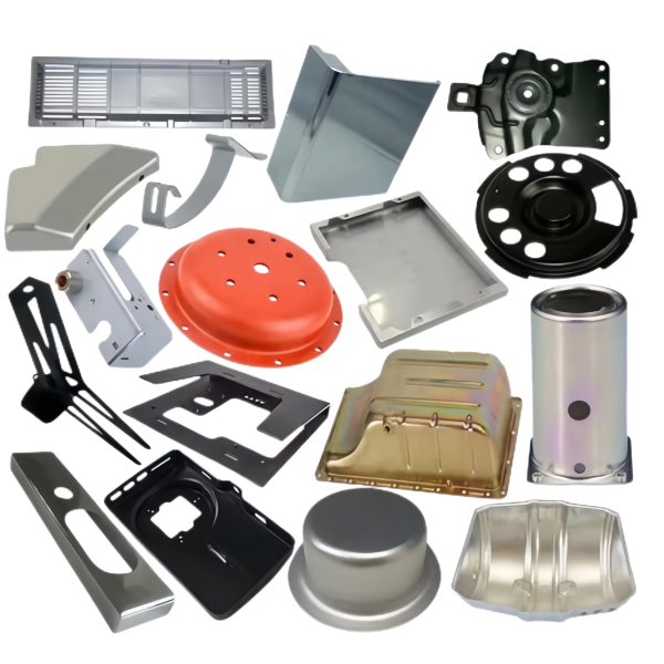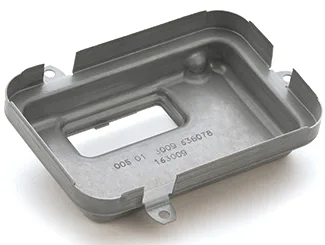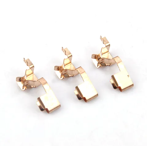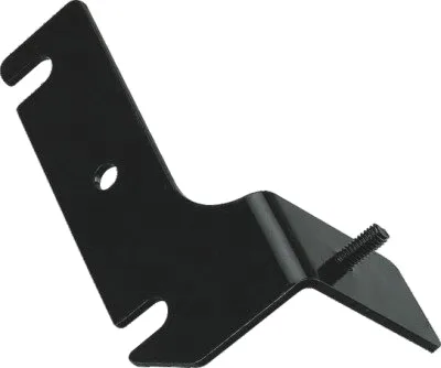
A black multi-bend mounting bracket is a black finish applied to a tolerance chain
A black stamped multi-bend mounting bracket does two things that are in tension. Structurally it is a small bracket with several bends, and every bend is a place where tolerance accumulates and springback moves the features. Cosmetically it is a black part, and a black finish on a small bent stamping is unusually sensitive to exactly those same bends – because bends are where coatings thin, bridge, and change the part’s apparent colour. Most of what makes this part difficult comes from the collision between those two requirements.
We stamp and form in a progressive die with minimal secondary work, on 5-250 T presses running progressive and compound dies, backed by CNC turning centres and a climate-controlled inspection room. Batch records are filed so a repeat order starts from approved data. Formed features to +/-0.05 mm and overall length to +/-0.1 mm, with dimensional reports accompanying the first article. Standard stock is carbon steel in SPCC and DC01 grades, 304 and 316 stainless steel, aluminium and brass, with mill certificates and heat numbers accompanying the first article. Surface treatment is matched to the duty, with alternatives quoted with the quotation and samples approved in writing. This page is about the tolerance chain on a bent part, and about why black on a multi-bend part needs more than one line of specification.
The tolerance chain on a multi-bend bracket
This is the core technical problem, and it is arithmetic before it is anything else. A bracket with four bends has four bend-position tolerances, and the distance between two features that are three bends apart is the sum of three bend positions plus a flat length. Add the tolerances worst-case and the achievable total is roughly three times the individual band. With bend positions at +/-0.05 mm, a feature-to-feature dimension spanning three bends can move by a tenth of a millimetre – which is often enough to stop the part assembling.
Four ways to reduce it, all of which are design decisions rather than manufacturing ones:
- Pierce every hole in the flat, before as many bends as possible. This is the most effective single move and it costs nothing. A hole pierced in the flat is located by a rigid tool; the same hole formed after three bends carries three bends’ errors plus its own.
- Shorten the chain. Rearrange the geometry so that the features that must relate to each other are separated by fewer bends. This is free at the design stage and expensive later.
- Constrain springback near the critical feature. A bead, a dowel, or a coined area near a bend locks the bend’s position and stops subsequent handling from moving it. It costs a station in the die and it is worth it where the feature is critical.
- Flag the critical dimensions and leave the rest general. A bracket with twelve dimensions does not need all twelve at +/-0.05 mm. Naming the two or three that are functional and relaxing the rest makes the part both cheaper and easier to hold consistently.
Springback, and why the material’s condition matters
Each bend springs back toward flat by an amount that depends on the material’s yield strength, the bend radius and the thickness. Two consequences on this part type:
- Angle tolerance has to allow for the material’s variation. Steel’s temper and grade vary the yield strength by a factor approaching two, and the springback varies with it. Where a bend’s angle is a functional requirement – where the bracket has to sit at a specified angle against a mating part – the material’s condition has to be confirmed, not assumed.
- The bend angle drifts as the tool wears. A forming punch’s radius and the die’s V-opening both change with wear, and the angle follows. On a bracket whose angle is critical, this is a periodic tool maintenance question, and on a bracket whose angle is only cosmetic it is not worth a maintenance interval. Knowing which kind of bend each one is tells you where to spend the tool budget.
Why black is a hard colour on a multi-bend part
Black coatings on a bent stamping create four distinct problems, and each is worth stating on the drawing as a requirement rather than being discovered:
- Bends thin the coating. The outside of a bend has more surface area per unit of projection than a flat, so coating builds differently there – and on a powder coat the bend often appears slightly lighter or slightly different in texture than the adjacent flat, because the powder’s coverage and the substrate’s curvature interact. On a small visible bracket this is the difference between “looks good” and “looks faulty”.
- Tight inside radii get bridged. A tight inside bend radius can be partially filled by a coating, which effectively removes the radius and creates a sharper corner than the drawing specifies. On a bracket this matters at a bend that has to clear another part.
- Gloss and texture interact with geometry. A textured black powder on a curved or bent surface shows its texture differently than on a flat, and two bends on the same part can read as slightly different colours to an observer. The standard response is a retained physical reference sample, agreed in writing.
- A coating changes dimensions on the bends. Overall length grows by roughly twice the film thickness at each end. At +/-0.1 mm overall length and an 80 micron powder coat, that is 0.16 mm of growth, which exceeds the band. Whether the length is before or after coating has to be stated.
Choosing the black finish for this part
| Powder coating | The usual choice for a black visible bracket. Hard, impact resistant, economical, any colour, any texture. Its thickness is the issue: 60-120 microns is more than this part’s formed-feature tolerance band, so every dimension the coating touches needs to be stated as post-coating, and tight clearances need masking. |
|---|---|
| E-coat | A much thinner, more uniform layer – typically 15-25 microns – deposited in a controlled bath. Uniform regardless of geometry and dimensionally much better behaved. It gives a slightly different appearance and a less robust film than powder, but on a small bent bracket where dimensions matter, it is often the better engineering answer. |
| Zinc plating with a black chromate conversion | Thin, dimensionally predictable, corrosion-protective, and it gives a genuine metallic black. It is the right answer where the bracket needs both corrosion protection and a black appearance at a tight tolerance. It is also a sacrificial coating that will eventually show white rust. |
| Anodising, passivation | For aluminium and stainless steel respectively, neither of which takes a black coating in the usual sense. Black on these is achieved by a dyed anodic layer on aluminium or by a black oxide or PVD-type treatment on stainless steel – both of which are different processes with different specifications. |
The decision that matters on this part type is whether the black finish has to coexist with tight dimensions. If it does, e-coat or a thin plating is the right answer. If it does not, powder gives a better-looking and more durable result and the drawing should simply be explicit about which dimensions are post-coating.
On a multi-bend bracket the grade interacts with both forming and finish
Standard stock is carbon steel in SPCC and DC01 grades, 304 and 316 stainless steel, aluminium and brass, with mill certificates and heat numbers accompanying the first article. On a multi-bend bracket the choice interacts with both the forming and the finish:
- Carbon steel is the standard. SPCC and DC01 both form well; DC01 has the tighter specification and is the better choice where a bend’s angle is critical or where the incoming material’s variation would move the features.
- Stainless Steel 304 or 316 springs back substantially more than mild steel and work-hardens faster across several bends, so the tooling has to be specified for it and the angle tolerance has to be wider. 316 for a corrosive environment.
- Aluminium springs back differently, is less stiff, and takes anodising rather than a black coating – so if the visual requirement is a specific black, aluminium constrains the finish options.
- Brass is formable, plates well, and takes a black plating – which is sometimes the cleanest route to a durable black on a small bent part.
Dimensional half and cosmetic half, kept separate
Eight things, and they split neatly between the dimensional half and the cosmetic half:
- Which dimension the part’s function depends on, flagged tighter than the rest, and the tolerance chain reaching it identified.
- Each bend’s inside radius, angle and tolerance, individually rather than by a general profile note.
- All holes located as true position to one datum, and pierced in the flat.
- The material’s grade and temper, confirmed in writing, particularly where a bend’s angle is functional.
- The finish system named – powder, e-coat, black chrome, dyed anodising – not just “black”.
- Colour against a retained reference sample, with texture and gloss stated together if the finish has a texture.
- Film thickness as a range, plus adhesion class if the part is visible.
- Which surfaces are masked, and which dimensions are before or after the coating.
And one habit worth adopting for this part type specifically: because the coating and the bends interact, an approved physical sample is worth more than any dimensional report on a small black multi-bend bracket. The sample carries the colour, the texture, how the coating looks on the bends, and the general visual impression – and it is the only specification that will settle an argument about whether the latest batch matches the previous one.
Custom Metal Stamping Parts is the range this part sits under; the overview page pulls together the tooling logic, finishing options and tolerance notes that apply across the family.
Specifications
| Item | Deep Drawn Sheet Metal Stamping Manufacturing Precision Deep Drawn Parts |
|---|---|
| Brand | AUNOV |
| Designing | Send drawings, or send a sample to be measured – unusual walls, threads or tolerances are feasibility-checked first; the approved drawing is kept as the controlled master. |
| Tooling | The tooling record travels with the part number, so maintenance history is never lost. |
| Samples | Samples are issued for approval before the run, and production starts only after written sign-off. |
| Materials | Standard stock: carbon steel (SPCC / DC01), 304 / 316 stainless steel, aluminium, brass; mill certificates and heat numbers accompany the first article. |
| Surface finish | Surface treatment matched to the duty: plating, coating or polishing; alternatives quoted with the quotation, samples approved in writing. |
| Processing | Stamping and forming in a progressive die with minimal secondary work; batch records are filed so a repeat order starts from approved data. |
| Equipment | 5-250 T presses running progressive and compound dies, backed by CNC turning centres and a climate-controlled inspection room. |
| Tolerance | +/-0.05 mm on formed features, +/-0.1 mm on overall length; dimensional reports accompany the first article. |
| Delivery terms | CIF or DDP, with FOB available, T/T or L/C, with D/P accepted on repeat business; sea or air freight is quoted to your door. |