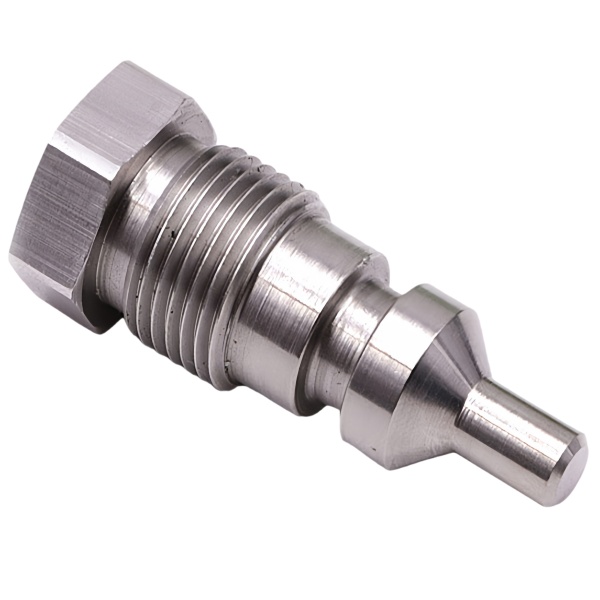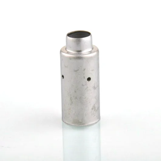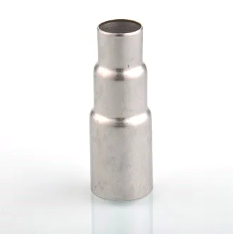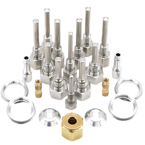
A welded end-closed temperature probe is the one sensor housing on this site where the manufacturing process is not a finishing step but the part’s reason for existing, and the weld is not a joint – it is a pressure boundary, a hermetic seal, and the thing that decides whether the probe measures anything at all.
So this page is mostly about weld quality requirements, because on this part the weld is a functional specification and “laser or TIG welding of formed components” is not enough to describe what has to be achieved.
Why the end is welded rather than drawn
Laser or TIG welding of formed components, dressing and leak testing, then finishing, with the tolerance at +/-0.05 mm on bend positions and +/-0.1 mm on blank outline. That tolerance band tells the story: this is a formed-and-joined part, not a machined one, and its accuracy is limited by forming and by the weld rather than by machining.
- A welded tip allows a heavier wall than a drawn tip. A drawn closed end is thinned by the punch, so a high-pressure or a high-temperature service needs a wall the drawing process cannot give. A tube with a welded end can be a heavier gauge, and that heavier gauge is the whole reason for welding.
- A welded tip allows a thicker tip than a drawn one. And a thicker tip holds pressure better and conducts worse – so welding buys pressure capability at the cost of response, and that trade is the design.
- And a welded joint can be made from materials that cannot be drawn together. A tube and a tip in different alloys, or a transition from one alloy to another where the process needs it.
The weld is a pressure boundary, which means three things
On a welded probe the weld has to satisfy pressure integrity, hermeticity, and fatigue resistance, and these are three different requirements with three different failure modes.
- Pressure integrity. The weld has to hold the process’s pressure without leaking. The relevant defects are porosity, incomplete penetration, and undercut – all of which are internal or subsurface and none of which are visible on the surface. So a visual inspection of the weld is not a pressure test, and a part that looks perfect can leak. This is the single most important thing on this page.
- Hermeticity. If the probe is sealed – and a temperature probe is often hermetically sealed so that the element is protected – then the weld’s requirement is far tighter than pressure integrity. A pressure boundary can tolerate a very small leak over a short duty; a hermetic boundary cannot, because the fill or the element will be contaminated over years. So a hermetic weld needs a leak test that is specified by leak rate, not by “holds pressure”.
- Fatigue resistance. A temperature probe in a vessel with thermal cycling sees the weld cycle. The weld’s heat-affected zone is the softest metal on the part and it is where a thermal fatigue crack starts. So the weld’s geometry matters – a smooth, gradual transition between the tube and the tip survives cycling better than an abrupt one.
Which process, and what each one is good at
The route allows laser or TIG. They are not interchangeable on this part, and the reason is specific.
- Laser welding on a thin-wall stainless steel tube and tip: fast, low heat input, a narrow and consistent weld bead, and therefore a small heat-affected zone. It is the better process for a thin-wall part and for a small tip. Its limitation is that it needs good access and good fit-up – a laser weld on a joint with a poor fit-up will be inconsistent, and on a drawn part’s slightly variable fit-up that is a real consideration.
- TIG welding on a heavier wall or where the access is poor: more heat input, wider bead, larger heat-affected zone, and better penetration on a thick section. It is the more forgiving process on fit-up. Its limitation on a thin wall is that it can burn through, and on a small part the heat input is hard to control.
- And on a probe the joint’s fit-up is a drawing consequence. A formed or drawn tube’s end is not as square or as clean as a machined one, so the joint’s preparation is a real operation and the weld process has to be chosen with that in mind rather than on the nominal wall alone.
Joint preparation, which is where a welded probe is won or lost
Four items, and all four are drawing or process decisions rather than welding decisions.
- The joint’s geometry. A butt joint between the tube’s end and the tip’s end is the strongest and the hardest to make well. A lap joint is easier to weld and weaker. Where the probe is a pressure boundary, a butt joint is the right answer and the preparation has to be machined rather than formed.
- The gap. A defined root gap, held by the fit-up, and the gap is what the process burns into. On a small probe the gap’s tolerance is in the tenths of a millimetre and it is a functional dimension – it affects penetration and it is the parameter most likely to vary on a formed part.
- The tube’s end condition. A drawn or sheared end carries the work-hardened and possibly oxidised layer from the forming. That layer has to be removed before welding or it will be in the weld and it will be a defect site. So the end’s preparation is a machining operation that often gets forgotten on a welded probe.
- And the cleaning. A stainless steel weld’s quality is very sensitive to surface contamination – and a drawn part that has been handled, or that has a forming lubricant on it, will weld differently. The cleaning step belongs on the routing sheet.
Dressing, and what dressing can and cannot fix
The route says dressing, and it is worth being precise about what that accomplishes.
- Dressing flattens the bead’s reinforcement and cleans the weld’s appearance. It makes the probe look right and it removes the stress concentration at the bead’s toe, which is a fatigue benefit.
- It does not fix porosity. A defect inside the weld survives dressing completely. So dressing improves the fatigue life and the appearance and does nothing at all for the leak path.
- And it must not take the wall below its minimum. On a thin-wall probe the dressing at the weld is where the wall gets thinnest, so the minimum wall at the dressed weld is a specification.
So the sequence on this part is: weld, then dress, then leak test – and the leak test is the one that verifies the weld rather than the surface. Where the weld is dressed to a controlled profile, that profile is a functional dimension because it is where the fatigue crack will start.
Leak testing, and what it has to be
The route says leak testing, and on this part the test’s specification is the thing that matters more than its existence.
- For a pressure boundary: a pressure or a leak test at a stated pressure, on every part. On a small probe this is quick on a test bench and it is the only test that verifies the weld.
- For a hermetic boundary: a helium leak test with a stated leak rate, or an equivalent. A pressure hold test on a small hermetic part can pass a part that will leak over five years, because the leak rates involved are below what a pressure decay test can resolve.
- And on a batch, a sampling plan with the sampling level stated – because a leak test that is destructive cannot be on every part, and a hermetic leak test is often destructive. So the plan has to state the sampling, the method, and the rate.
Where there is heat input, the L grade is the metallurgical answer
Materials held include carbon steel, 304 and 316 stainless steel, aluminium and brass, with grade and temper confirmed before tooling. On a welded probe the grade’s weldability is not a secondary consideration – it is a requirement.
- 316L rather than 316 wherever the probe will be welded, and this is the specific reason: the low carbon resists sensitisation in the weld’s heat-affected zone. A probe welded in ordinary 316 has a corrosion initiation site inside its pressure boundary, and on a probe that will be in a corrosive process that site will become a leak over years.
- 304 is weldable and is the answer where the process is benign. It is more prone to sensitisation than the L grades, and on a welded probe in a corrosive service that is worth avoiding.
- Brass welds easily and is used on low-pressure and moderate-temperature probes, and its limitation on a hot or aggressive service is dezincification – and a dezincified probe on a pressure boundary is a weakening part that can fail without warning.
- Carbon steel where the service is benign, with the weld’s quality being a larger factor than on the stainless steel because the weld’s own properties govern the joint and a poorly made weld in a pressure boundary is the failure.
Tolerance, and why the band is loose
+/-0.05 mm on bend positions and +/-0.1 mm on blank outline, with dimensional reports accompanying the first article. Those numbers look loose compared with the machined parts on this site, and they are correct – because on a formed-and-joined probe the limiting factors are the forming and the weld, not the machining.
- What should be tighter than the general band: the probe’s length, because it is the immersion depth and the immersion depth is the accuracy. And the tip’s position relative to the datum, for the same reason.
- What can be at the general band: the outline, the bend positions, anything cosmetic.
- And what is not a dimension at all but matters more than all of them: the weld’s quality and the leak rate. Those are the two specifications that decide whether this part functions, and neither appears as a tolerance.
Hermetic, or only good enough to hold the process pressure?
Is this probe hermetic, or does it just need to hold the process pressure – and what is inside it? Two questions, and they decide the weld’s specification. If the probe only has to hold the process’s pressure, then a pressure hold test on every part is sufficient and the weld is specified by its process and its penetration. If the probe is hermetically sealed – which is common on a temperature probe where the element has to be protected for years – then the weld has a leak-rate requirement that a pressure hold test cannot verify, the testing is likely to be destructive, and the sampling plan has to be agreed. And the second question decides something else: a hermetically sealed probe has trapped gas or trapped fill, and that has a thermal consequence and a pressure consequence as the temperature changes. So the honest follow-up is: is there a vent, or is the cavity filled with something that can accommodate the thermal movement? On a welded probe this question is structural rather than cosmetic, because there is no disassembly path – once it is welded, whatever is inside stays inside, and whether that is acceptable depends entirely on what it is and what it will be doing at the service temperature.
Custom Metal Stamping Parts is the parent range for parts like this one; the overview page gathers the tooling logic, finishing options and tolerance notes that apply across the family.
Specifications
| Item | Custom End Closed Welding Stainless Steel Temperature Sensor Probe |
|---|---|
| Brand | AUNOV |
| Designing | Design intent is read from the print, and any conflict in the drawing is raised before quoting. |
| Tooling | Dies, fixtures and gauges are made in our own toolroom, so a die can be re-cut against the approved drawing, and first-article timing is measured from the tooling start date. |
| Samples | Prototype and pre-production samples are provided against the drawing, so the sample is retained as the master, and production starts only after your written sign-off. |
| Materials | Materials held include carbon steel, 304 / 316 stainless steel, aluminium and brass; grade and temper are confirmed in writing before tooling. |
| Surface finish | Natural, plated or coated – the print decides, and the agreed finish is logged; finish thickness and adhesion checked on the first article. |
| Processing | Laser or TIG welding of formed components, dressing and leak testing, then finishing. |
| Equipment | Press shop with 5-250 T mechanical presses and dedicated dies, backed by CNC turning centres and a climate-controlled inspection room. |
| Tolerance | +/-0.05 mm on bend positions, +/-0.1 mm on blank outline; dimensional reports accompany the first article. |
| Delivery terms | Delivery quoted per Incoterms 2020 – FOB, CIF or DDP – by sea or air, to your address. |