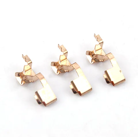
A terminal clip is an electrical contact pretending to be a piece of metal
A brass stamped terminal clip contact has a job that is much more specific than its shape suggests: it is the last mechanical and electrical connection in a circuit, and it has to do both at once. Electrically it is a defined contact resistance over a defined life. Mechanically it is a spring that has to hold itself against a mating part. Every design decision on this part follows from the fact that those two requirements are met by the same piece of metal at the same two contact points.
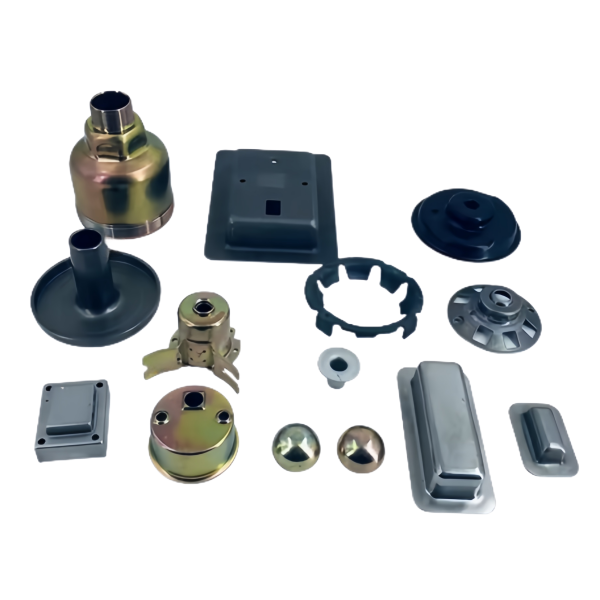
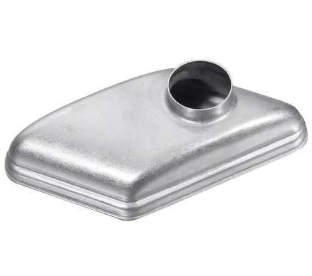
On this part we deep draw on maintained presses with blank size and lubrication logged per run, and first articles verify the whole flow before the run is released. Press capacity is mechanical 5 to 250 T and hydraulic 250-500 T with in-line annealing furnaces, first articles and batch samples checked on the CMM. Turned secondary features to +/-0.03 mm and as-drawn walls to +/-0.1 mm, with finer bands confirmed from capability data before quoting. Materials held include carbon steel, 304 and 316 stainless steel, aluminium and brass, with material substitutes proposed only with your written approval. Finish is selected from the drawing – plating, coating, anodising or passivation – with masking and laser marking available where needed. This page is about contact resistance, spring force, and the four things that decide whether this part lasts.
Contact resistance is a surface property, not a metal property
What makes a terminal conduct is the surface. Oxide films, organic films, and any contamination from the stamping process all sit between the two contacts and dominate the resistance. This is why the finishing specification on this part matters more than the material choice:
| Tin plating | The standard for low-current connections. Tin is soft, it deforms to make a larger real contact area, it resists corrosion well, and it is solderable. Its weakness is whisker growth over time, which can eventually produce a resistive joint – a real phenomenon that matters in long-lives, high-reliability applications. |
|---|---|
| Gold plating | For very low contact resistance, very low current, or where a coating must not oxidise at all. Gold does not tarnish, which removes the main variable. It is expensive and it is soft, so it wears – which is fine for a low-force contact but is not the answer for a high-wear position. |
| Silver plating | The best electrical conductivity of the common contact platings, and it oxidises less than most. It tarnishes in sulphide environments, and it suffers from a well-known migration issue under certain conditions. |
| Nickel plating | Hard, wear-resistant and corrosion-resistant. It has higher contact resistance than tin, gold or silver, so it is used where mechanical durability matters more than a very low resistance – and where the contact force is high enough to break through any film. |
| Uncoated brass | Acceptable for a low-current, dry, protected connection. Brass itself has good conductivity and its oxide is manageable, but a bare surface will have a higher and less stable contact resistance over time than a plated one. |
The rule that follows: the contact’s plating is chosen for the electrical requirement and the environment, and the drawing must state which plating rather than accepting a default. And because plating grows on the part, the contact geometry has to be specified post-plate – which is a dimensional decision, not a finishing one.
Spring force, and the contact’s other job
A terminal clip holds itself against a mating part, and that force is what keeps the electrical contact stable. Four things determine it, and all four are worth getting onto the drawing:
- Material and its condition. The contact force comes from elastic deflection, so it is limited by the material’s yield strength. On brass this is affected not only by the alloy but by the temper – and a drawn, work-hardened clip has a different and higher spring rate than an annealed one. The temper should be confirmed in writing.
- Section thickness. Force scales with thickness cubed in a bending clip. This makes the material’s thickness tolerance a force tolerance, and it is the most common cause of an inconsistent batch.
- Length and width. Deflection scales with the cube of length, so a small length error produces a larger force error.
- Contact geometry. A domed or crowned contact concentrates the force into a small area, which lowers the resistance but raises the wear rate. A flat or radius contact spreads the load. The choice is a design decision about whether this contact is expected to move.
Insertion, cycling and wear
A terminal clip is mated and unmated, sometimes many times, and this is where the design is tested:
- Insertion force has to be high enough to hold the contact together and low enough that the mating part can be inserted without damage – often without a tool. A clip that needs force to insert will be inserted once.
- Wiping action. On every mating, the contact surfaces slide against each other microscopically. This wipes the contact clean – which is genuinely useful and removes oxide – but it also wears the plating. A gold contact on a high-cycle application wears through, and a tin contact works for a much higher cycle count because it is soft and deforms to maintain contact.
- Fatigue. A spring clip that flexes many times can work-harden and take a permanent set, losing force. The number of cycles and whether the force must be maintained over them are requirements worth stating.
- Stress relaxation. In a slightly elevated temperature environment, a clip under constant deflection relaxes and loses force over time. On a terminal near a heat source this is a real effect and the temperature belongs on the drawing.
Brass, and why it is the default here
Carbon steel, 304 and 316 stainless steel, aluminium and brass are all held, with substitutes only by written approval. For a terminal contact, brass wins on almost every count:
- Conductivity. Brass conducts well – better than stainless steel by a wide margin and better than steel, though not as well as copper. For a contact where the plating carries most of the current, this is not critical; where the body carries current, it matters.
- Corrosion behaviour. Brass is stable in ordinary atmospheres and in many mild chemical environments. It does dezincify in acidic or ammonia-bearing conditions, so it needs specifying for the medium rather than for the application.
- Formability. Brass draws and stamps well into the thin-walled spring shapes this part needs, and it work-hardens usefully.
- Machinability. Where a secondary feature needs to be turned, brass is straightforward.
When brass is the wrong choice: in a high-temperature position where stress relaxation matters, where a much higher contact force is needed because of a severe environment, or where the current level makes brass’s conductivity marginal. In those cases a copper-clad or a plated-steel construction is the usual answer, and it is worth raising at review.
Drawing this part
The drawing’s job is to specify a force, a resistance, a plating, and a mating hole – four different things, only one of which is a dimension. What belongs on it:
- The plating, stated explicitly – tin, gold, silver or nickel – with its thickness or thickness class, and whether dimensions are before or after plating.
- The retention or normal force, stated as a force rather than as a dimension, and whether it applies before or after plating, because the plating changes it.
- The mating part, or at least its hole size, wall thickness and material. The contact’s force and resistance are properties of the pair.
- The cycle count and whether the force must be maintained across it.
- Which surfaces are masked. A contact surface that gets masked from plating has no plating on it at all, and a terminal body that gets plated where a wire is crimped changes the crimp’s geometry.
- The crimp or wire attachment, if there is one – its hole size, whether the hole is plated, and how it is specified.
Production controls, and why they are logged
Blank size and lubrication logged per run is a specific and deliberate control on this part. Both variables directly affect a drawn thin-walled contact: the blank’s size sets the wall’s thickness and the draw ratio, and the lubrication affects friction at the die – which affects both the wall’s thinning and the force the material ends up with. Recording both per run means a question about a batch six months later has an answer.
First articles verify the whole flow before the run is released, and first articles and batch samples are checked on the CMM. Turned secondary features at +/-0.03 mm cover any machined contact feature, and finer bands on the contact geometry are confirmed from capability data before quoting – which on a part whose entire function is a contact is worth asking for, because a contact’s capability is a force and resistance spread rather than only a dimensional one.
Finish is selected from the drawing with masking and laser marking available, and laser marking is genuinely useful here: where a terminal clip carries a high current or where traceability matters across a large assembly, marking the part number or lot on the contact body is cheap insurance and takes one operation.
The engineering calls behind a part like this — draw ratio, wall thinning, radii and trim — each get worked examples in our deep drawn covers guide; the Precision Deep Drawn Parts pages gather the rest of the family.
Specifications
| Item | Custom Heat shields for Automotive Parts Double Layer Deep Drawn Parts |
|---|---|
| Brand | AUNOV |
| Designing | The drawing is reviewed first; the agreed version then governs every batch. |
| Tooling | Tooling is designed and built in house and held under your part number, so the die stays dedicated to your part. |
| Samples | Sample parts are measured and reported before submission, so the approved first article becomes the gauge reference, and production starts only after your written sign-off. |
| Materials | Materials held include carbon steel, 304 / 316 stainless steel, aluminium and brass; material substitutes are proposed only with your written approval. |
| Surface finish | Finish selected from the drawing: plating, coating, anodising or passivation; masking and laser marking available where needed. |
| Processing | Deep drawing on maintained presses, blank size and lubrication logged per run; first articles verify the whole flow before the run is released. |
| Equipment | Mechanical presses from 5 to 250 T and hydraulic presses 250-500 T, with in-line annealing furnaces; first articles and batch samples are checked on the CMM. |
| Tolerance | +/-0.03 mm on turned secondary features, +/-0.1 mm on as-drawn walls; finer bands confirmed from capability data before quoting. |
| Delivery terms | FOB Ningbo or Shanghai, T/T with deposit and L/C for larger runs; sea or air freight is quoted to your door. |