

The oxygen sensor shell: thin metal holding a ceramic at 800 °C
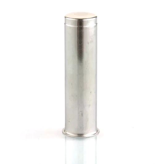
Inside an oxygen sensor, a ceramic element does the measuring – and it is brittle, temperature-sensitive, and has to be held in exactly the right position within the exhaust gas stream. The oxygen sensor shell is what holds it: a thin drawn metal shell that grips the ceramic, transmits the exhaust’s heat to it, seals around it, and survives the thermal cycling that would crack a rigid mounting. This page covers the shell’s role as the ceramic’s mechanical and thermal interface, which is where its design decisions actually live.
Holding a brittle element without cracking it
A ceramic sensing element cannot be clamped rigidly: differential expansion between the metal shell and the ceramic will crack it as temperature changes. The shell’s design therefore accommodates movement – through the geometry of the seat that receives the element, through a compliant interface layer (a packing, a talc seal, a flexible metal element), and through the shell’s own compliance in the radial direction. A shell that is too stiff in the wrong place, or whose seat is dimensioned so the ceramic is pinched, will crack elements in the field in a pattern that looks like a material failure but is a mounting problem. Our shells are dimensioned as a system with the customer’s element and interface layer, with the seat’s bore and depth agreed so the ceramic’s seating load is controlled, and validated by thermal cycling the assembled sensor and inspecting elements at intervals.
The shell’s thermal job
The shell connects the ceramic to the exhaust’s heat, and for a sensor that is not actively heated, this heat path determines how quickly the sensor reaches operating temperature after a cold start. That is an emissions-relevant parameter: a sensor that warms slowly keeps the engine in open-loop fuelling longer. Shell thickness and its contact with the element set how fast the heat arrives, and thinner shells with good contact reach temperature faster. For actively heated sensors the shell’s job changes slightly – it must not short the heater’s circuit or drain its heat away – which places requirements on the shell’s material and its electrical isolation from the heater and signal paths. We ask for the sensor’s heating architecture at RFQ, because it changes the shell’s design rather than merely its dimensions.
Sealing around the ceramic
The shell seals the exhaust gas away from the sensor’s interior, where the electrical connections live. That seal is formed around the ceramic element and must survive the same thermal cycling as everything else: it is typically achieved by a compressed packing or a talc-based seal whose compression the shell’s geometry controls. We form the shell’s sealing features – the grooves, seats and crimps that compress the seal – to dimensions agreed with the sensor maker, and validate the seal by leak testing assembled sensors through thermal cycles. A seal that passes at assembly and leaks after cycling is the classic failure here, and it is prevented by compression sized for the hot condition and by geometry that does not let the packing migrate.
Thin walls in a hostile place
Sensor shells are thin – fractions of a millimetre – and thin walls in an exhaust environment are a challenge: they must resist oxidation, maintain their shape through cycling, and hold the ceramic without distorting. Forming such shells from heat-resisting stainless steel requires careful draw sequences, because the high-alloy grades work-harden and the thin walls offer little margin for error. Our approach uses generous radii where geometry allows, verified wall thickness at critical sections, and heat-resisting grades matched to the sensor’s location. Where a design’s wall is thinner than the draw can reliably produce with the required grade, we will recommend a slightly thicker section rather than quote a process that produces cracks in production.
A seat that pinches the ceramic, or a shell too stiff
The shell drawing with the element’s seat geometry, the seal’s print and the sealing feature dimensions, the heater architecture, the wall thickness; the sensor’s exhaust position and peak temperature (for grade selection); the leak and thermal cycling requirements; and volume. First articles in four to five weeks after die approval, with seat metrology, wall thickness mapping, leak checks and thermal cycling where specified.
Elements crack in service – is the shell at fault?
Our elements crack in service – is the shell at fault? Often yes, if the seat pinches the ceramic or the shell is too stiff locally so cycling loads the element. Send the failed assemblies; the crack pattern and the seat’s metrology usually identify the problem within a week.
Can you make the shell thinner to improve warm-up? Within limits – the draw and the grade set a floor, and going below it produces cracks. We will quote the thinnest wall we can hold reliably with your grade and show the trade.
Do you assemble the shell with the element? On qualifying volumes we can assemble and leak-test to your specification, which moves the delicate ceramic handling to a controlled process. The element remains your part and your specification.
Our Sensor Housings range is where this part sits. The sensor housings pages carry the process notes, common materials and inspection points behind every product in the family.
Specifications
| Item | Oxygen sensor shell |
|---|---|
| Brand | AUNOV |
| Designing | Quotation is built from the drawing: DFM notes come back with the price rather than after tooling. |
| Tooling | Tooling is built and held under your part number, so the die charge appears as its own quotation line, and the die remains dedicated to your part. |
| Samples | Sample parts are measured and reported before submission, so any deviation is corrected at sample stage, and the signed sample is kept for future reorders. |
| Materials | Carbon steel, 304 / 316 stainless steel, aluminium and brass are all held in stock; special grades are sourced to the drawing when volumes justify. |
| Surface finish | Plating, coating or polishing to suit the drawing; the agreed finish travels with the part number. |
| Processing | Deep drawing first, CNC finishing on critical faces after; first articles check the complete flow before we release the run. |
| Equipment | Hydraulic drawing presses and CNC lathes for sealing faces; first articles and batch samples are checked on the CMM. |
| Tolerance | +/-0.01 mm on sealing faces, +/-0.05 mm on drawn profiles; dimensional reports accompany the first article. |
| Delivery terms | FOB, with DDP offered for EU and US addresses, T/T with deposit and L/C for larger runs; each volume tier carries its own quoted price. |
Frequently Asked Questions
What is the shell holding, and why is that the difficulty?
The ceramic element that does the measuring. It is brittle, it does not tolerate point loading, and it has to sit in exactly the right position inside moving hot gas. The shell therefore has to locate something fragile accurately while itself being the structure that survives the environment, which puts the two demands of the part directly against each other.
Which is worse for the element – a seat that pinches it or a shell that is too stiff?
Both fail, but the second is harder to diagnose. A seat that pinches cracks the ceramic directly and usually shows where. A shell that is too stiff transmits its own thermal and assembly strain into the element instead of absorbing it, cracking it just as effectively with no offending feature afterwards to point at. Providing compliance where the element sits is the requirement most often missing.
Where does the seal around the ceramic have to hold?
On both sides at once, selectively. Gas has to reach the sensing face and stay away from everything behind it, which makes the element the divider. The seal therefore has to be gas-path selective rather than simply gas-tight, which is why this interface is specified by what reaches where instead of by a blanket sealing requirement.
Why do thin walls survive here when they would not elsewhere?
This is one of the few places where thin is the design rather than the compromise. Thin metal moves heat quickly, keeps the element close to the gas it measures, and flexes enough not to load the ceramic. The penalty is that it carries almost no margin against damage in handling and assembly, which is why those two activities deserve more attention than the material call-out.
Related Products



Request a Quote for This Part
Send a drawing or sketch — get material advice, tooling cost and a per-piece price within 24 hours (working days).