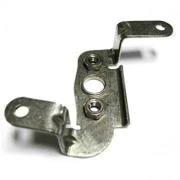
A Z-bracket holds by geometry, and geometry is what wears out
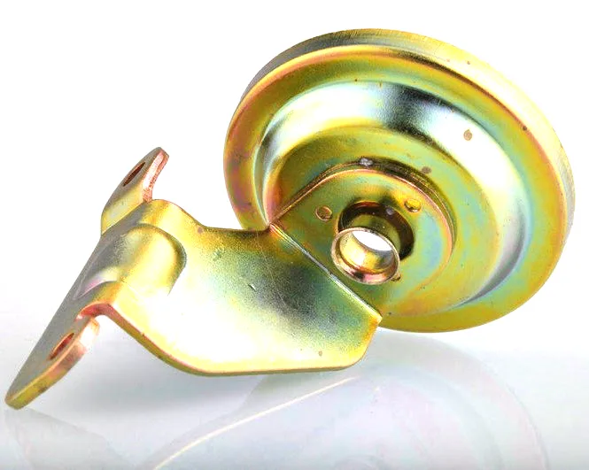
A galvanized steel stamped Z-mounting bracket gets its name from its profile – the section is a Z, with two flanges at the ends pointing in opposite directions. That geometry is the whole point: a Z-section is what lets a bracket bolt to a surface on one side and hold a component on the other while sitting clear of the surface in between. It is one of the most efficient shapes in stamping for absorbing bending in one plane, and it is used for cable clamps, pipe supports, sensor mounts and panel fittings precisely because it does that efficiently and cheaply.
On this part we stamp and form in a progressive die with minimal secondary work, on 5-250 T presses running progressive and compound dies, with CNC turning centres for secondary operations and CMM inspection. Batch records are filed so a repeat order starts from approved data. Tolerance runs +/-0.05 mm to +/-0.1 mm across the part, with capability checked on the first article before the run continues. Carbon steel, 304 and 316 stainless steel, aluminium and brass are held in stock, with material substitutes proposed only with your written approval. This page is about what a Z-section actually does, where it fails, and what a drawing needs to say about it.
Why a Z works, and what it costs
A Z-section is a beam with its material placed away from the neutral axis in both flanges, and the geometry gives it three useful properties:
- Efficient bending stiffness for the material used. Because both flanges contribute at maximum distance from the neutral axis, a Z is far stiffer in bending than a flat strip of the same weight and thickness. This is the main reason it is used.
- Offset mounting surfaces. The two flanges are parallel but face opposite directions, so the bracket can bolt flat to one surface and hold something against another, with clearance between them. A channel would also give clearance but only one flange orientation; the Z gives two, which is what allows it to clamp something against a face while standing off.
- Symmetry that hides the twist. A Z-section is symmetric about its centre, so a load applied off the centreline tends to produce a symmetric deformation rather than a twist. That is why Z-brackets are common in applications where a channel would roll.
The cost is worth stating: a Z-section only works in one plane. Loaded in the other plane, it has almost no stiffness, because the flanges are edge-on. A bracket that might see load from an unexpected direction needs either a different section or a second Z rotated against the first.
Where a Z-bracket fails
Four failure modes, all traceable to a detail on the drawing:
- Flange curl. The flanges of a formed Z are under residual stress from bending, and they curl. On a bracket that has to sit flat against a surface, a curled flange means the bracket rocks or does not seat. The cure is a flatness requirement on the flange, and a forming plan that manages it – which usually means a coining or a sizing operation on the flange.
- Distortion at the bends. Two bends in a thin bracket produce out-of-plane bow. On a part with a hole pattern, the bow shifts the hole positions relative to the mounting face – the classic progressive-die distortion problem.
- Cracking at the bends. The inside radius of each bend is where the outer fibre is stretched most. A tight radius on a thicker or harder material will crack, and a cracked bend is a scrapped part rather than a marginal one.
- Galvanizing thickness. On a bracket specified as galvanized, the coating adds to every dimension and the flange’s flatness can be affected. This is a bigger deal for a Z than for a flat part because the flanges are the sealing-or-seating surfaces that make the geometry work.
The drawing decisions that matter
On a Z-bracket the tolerance structure follows from the fact that the two flanges and the web form a shape that has to stay square:
- Flange flatness stated against a named surface, because that is what determines whether the bracket seats.
- Bend positions held to +/-0.05 mm, since they set where the flanges land and therefore the bracket’s standing-off height.
- The web’s height – the Z’s depth – stated with a tolerance, because the whole point of the section is its depth and a shallower Z is a different bracket.
- Hole positions relative to the mounting face, as true position to a datum, because distortion from the bends moves them.
- The mating hole pattern, if there is one, because the bracket’s holes have to align with something.
Materials and the environment
Carbon steel, 304 and 316 stainless steel, aluminium and brass are held in stock, with material substitutes proposed only with your written approval. On a Z-bracket the material choice is mostly about the environment and about formability:
- Carbon steel. The standard choice, and the one the galvanized version uses. It forms easily, the section is stiff for its weight, and it needs coating for any moisture exposure.
- 304 or 316 stainless steel. For wet, outdoor or corrosive exposure. Stainless Steel is harder to form and springs back more, so the flange angle needs a tolerance that allows for it and the tooling has to be specified for it. 316 for salt or chloride environments.
- Aluminium. Where mass matters. Its modulus is a third of steel’s, so an aluminium Z-section needs a noticeably greater depth to achieve the same stiffness – worth working out before the design is fixed, because a shallower section than the steel version is a common and expensive mistake.
- Brass and copper. Where conductivity or a specific corrosion behaviour applies.
Surface finish and the galvanized question
Surface treatment matched to the duty – plating, coating or polishing – with finish thickness and adhesion checked on the first article. For a galvanized Z-bracket specifically, three things follow from the coating:
- Flange thickness grows, and the two flanges grow in opposite directions relative to the bracket’s centre. On a bracket that fits between two surfaces, that growth closes the gap. The drawing should state whether the standing-off height is before or after coating.
- Coverage at the bends is thinner, and the bends are where the coating bridges from one flange to another. This is a genuine corrosion initiation site on a Z-bracket, because the bend is on the outside of the profile and is exposed.
- Flange flatness can be affected, and if the bracket must seat flat, the coating’s effect on that has to be accounted for rather than assumed away.
Where a galvanized bracket is specified, hot-dip galvanising gives a much thicker and less uniform coating than electroplating, and the two are not interchangeable on a part with a fitted dimension. Electroplated zinc is generally the right choice for a small stamped Z where the geometry is tight.
Progressive die: why it suits this part
Stamping and forming in a progressive die with minimal secondary work is exactly the right process for a Z-bracket, for three reasons:
- The bends happen in the flat-ish stages. A progressive die forms the Z progressively as the strip advances, and the geometry is built up in the correct sequence. This is cheaper and more consistent than bending a finished part.
- Holes are pierced while flat, which is where position accuracy is best – and on a part whose whole purpose is a hole pattern, that matters.
- High volume economics. A progressive die runs hundreds of strokes a minute with no operator involvement, and the piece cost is dominated by material and die amortization. On a bracket, which is a small part, that is the difference between a viable and an unviable price.
Coil thickness and die condition decide a bent part’s repeatability
Batch records are filed so a repeat order starts from approved data, which on a bracket with a bent section is worth having – the two variables that most affect a bent part’s repeatability, the incoming coil’s thickness and the die’s condition, are both process inputs rather than drawing features.
Seven things to settle on a Z-bracket drawing:
- The section depth stated as a dimension, not implied by a profile view.
- Flange flatness against a named surface.
- Bend positions and the standing-off height they produce.
- Inside bend radius specified, so the corner does not crack.
- Whether the load is in the Z’s strong plane, and what happens if it is not.
- Hole positions as true position to a datum, and the mating pattern.
- Whether dimensions apply before or after coating, on anything the coating will change.
And one question worth asking at review: does the bracket need a full Z, or would a simple offset bracket – two flanges with a single offset – do the job. A Z-section is more efficient in bending and less efficient everywhere else, and on a lightly loaded bracket the simpler offset form is cheaper to tool, easier to form, and less prone to curl. If the load is light, that is often the better answer.
Custom Metal Stamping Parts is the parent range for parts like this one; the overview page gathers the tooling logic, finishing options and tolerance notes that apply across the family.
Specifications
| Item | Custom Deep Drawn Stamping Parts Sheet Metal Fabrication |
|---|---|
| Brand | AUNOV |
| Designing | Quotation follows the print, not a catalogue – samples are reverse-measured into a controlled drawing; changes are priced before they are made. |
| Tooling | Progressive and drawing dies are designed and built in house, so the die charge appears as its own quotation line, and ownership is confirmed on the quotation. |
| Samples | Sample lead time is quoted with the order, and the approved sample governs the run. |
| Materials | Carbon steel, 304 / 316 stainless steel, aluminium and brass are all held in stock; material substitutes are proposed only with your written approval. |
| Surface finish | Surface treatment matched to the duty: plating, coating or polishing; finish thickness and adhesion checked on the first article. |
| Processing | Stamping and forming in a progressive die with minimal secondary work; batch records are filed so a repeat order starts from approved data. |
| Equipment | 5-250 T presses running progressive and compound dies, with CNC turning centres for secondary operations and CMM inspection. |
| Tolerance | +/-0.05 mm to +/-0.1 mm across the part; capability is checked on the first article before the run continues. |
| Delivery terms | Shipping terms are set with the order: FOB, CIF or DDP, T/T or L/C, door delivery quoted. |