A slotted mounting channel is a tolerance absorber, and that is a design decision with a price
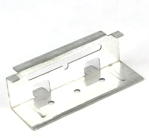
A slotted stainless steel stamped mounting channel is a channel section with a slot – or a row of slots – along it, and the slot is the whole point. A plain channel mounts with fixed holes and requires the mounting structure’s hole positions to match exactly. A slotted channel tolerates a position error along the slot’s length, which converts an assembly problem into a slide. That is a genuinely valuable feature, and it is also a decision with real costs: the slot weakens the section, the slot’s ends are stress risers, and a channel designed around a slot is a different structure from a channel designed without one.
We coil-blank and progressively draw, coining on the final station where the print calls for it, and first articles verify the whole flow before the run is released, on 5-250 T mechanical presses and 250-500 T hydraulic presses with annealing furnaces in line, and first articles and batch samples checked on the CMM. Turned secondary features to +/-0.03 mm and as-drawn walls to +/-0.1 mm, with GD&T per the drawing and PPAP-style reports on request. The material is 1050, 3003, 5052 or 6061 aluminium in 0.5-3.0 mm stock with the temper matched to the forming depth or machining route – and where the drawing says stainless steel for the part itself, 304 and 316 are the practical choices. Natural, plated or coated per the print, with the agreed finish logged and the agreed finish travelling with the part number. This page is about the slot: what it buys, what it costs, and how to dimension it.
What the slot actually buys
The value of a slot is tolerance absorption, and it is worth being precise about how much it absorbs, because a common misunderstanding here costs real money.
A fastener in a round hole has to satisfy the fastener’s clearance – typically 0.6 to 1.0 mm of diametral movement for an M6 in a nominal clearance hole. A fastener in a slot can move along the slot’s length by the slot’s width minus the fastener’s diameter, plus its normal clearance. So the slot’s width is the design variable, and the length is just how far the installer can place it.
- A slot wider than the fastener’s clearance hole gives most of the benefit and no more. A slot 0.8 mm wider than the fastener’s diameter absorbs 0.8 mm of position error. Widening it further absorbs more, and eventually the slot becomes long enough that the channel no longer holds the fastener properly.
- A slotted hole also stops the fastener rotating under tightening, because the slot’s ends are a positional constraint. This is a genuine bonus on a vibration application and is sometimes the main reason the slot is there.
- It does not absorb error in the other direction. A slot is one-dimensional. Error perpendicular to the slot still has to be absorbed by the clearance, and if that is tight the part will not assemble. This is the limitation people forget, and it is why a design that needs tolerance in two directions needs two features.
- It does not absorb rotational error about the channel’s axis, and it does not absorb a mounting structure that is simply in the wrong place.
What the slot costs
- Section stiffness. A slot removes material from the web, and the web is where a channel carries its shear. A wide slot in a short channel removes a significant fraction of the section, and the channel’s stiffness drops much more than the material removed would suggest because the slot also interrupts the load path’s continuity.
- Stress concentration at the slot’s ends. The ends of a slot are where the stress from a loaded fastener is highest, and under cyclic load they are where a crack starts. A slot with square ends is worse than one with radiused ends, and a slot with generous radii can be made nearly as strong as a plain hole.
- Burrs at the slot’s ends. A pierced slot leaves two ends with sheared edges, and these are where a hand will find the sharp edge and where a fatigue crack will start.
- Press tool cost. A slot is a piercing operation with a shaped punch, and a long slot on a thin wall needs care to avoid distortion. It is a real additional tool feature.
Slot geometry: the four things to specify
This part type has a tight band on turned secondary features at +/-0.03 mm, and on a slotted channel the features that need it are the slot’s edges and the channel’s mounting faces. The four slot dimensions, all of which should be on the drawing:
- Slot width, as a size and a tolerance, because it is the tolerance-absorption variable and because it determines the fastener’s position within it.
- Slot length, and more usefully the position of each slot’s centre from the channel’s datum, because that is what determines the assembly’s flexibility along the channel.
- Slot end radius. Not a detail. A radiused slot end is materially stronger than a square one and it removes the stress concentration and the hand-laceration hazard in one change.
- Edge distance from the slot to the channel’s edge, which sets how much material remains to carry load around the slot. A slot close to the channel’s edge or its bend will tear there instead.
Forming the channel, and what the draw changes
A channel is a formed section with two bends, and a slotted channel has those bends plus a piercing. Three points about the sequence:
- The channel’s bends set its section’s geometry, and springback in the bends changes the channel’s width and its squareness. A channel that is not square will not sit flat, and on a slotted channel where the slots are the mounting feature, the slot’s position relative to the mounting face is what matters – so the bends’ springback has to be managed before the slots are located.
- The slot is best pierced in the flat, before the bends. A slot pierced in a formed channel is located on a curved or a bent surface, and its position accuracy is worse – and on a slotted channel the slot’s position along the channel is exactly the feature that must be accurate.
- Coining on the final station, where the print calls for it, brings the channel’s section and its mounting face into a controlled band. On a slotted channel this matters more than on a flat bracket, because the channel’s flatness is what determines whether a fastener in a slot bears on the channel’s face properly.
Stainless Steel versus aluminium on this part
The material line covers 1050, 3003, 5052 and 6061 aluminium with the temper matched to the forming depth or machining route, and the product is described as a stainless steel stamped channel – so the practical choice is between the two, and it is a real decision rather than a default.
| 304 stainless steel | The standard for a slotted channel. Excellent corrosion resistance, stiff for its section, and it holds its formed geometry better than aluminium. The trade is heavier, more expensive, and harder to form – so it needs more generous bend radii and its springback has to be compensated for more thoroughly. |
|---|---|
| 316 stainless steel | For chloride exposure – salt air, marine, de-icing, washdown. The correct answer for an outdoor or coastal channel and a common and expensive mistake to use 304 there. |
| 3003 aluminium | Light and formable, and it takes a good surface. Its modulus is a third of steel’s, so an aluminium channel has to be materially deeper or thicker to have the same stiffness – and on a channel whose section is already designed around a slot, that is a significant change. It also relaxes under sustained clamping load, which matters where a channel is tightened once and left. |
| 5052 aluminium | Stronger and better for corrosion, at the cost of formability and surface finish. Worth it where the channel carries load. |
On a slotted channel specifically, stainless steel’s better retention of stiffness and better behaviour under sustained clamp load make it the better engineering answer unless mass is a dominant requirement.
A fastener bearing on a slot’s faces needs them left bare
Natural, plated or coated per the print, with the agreed finish logged and travelling with the part number. On a slotted channel the finishing requirements are specific and functional:
- The slot’s faces. A fastener sliding in a slot bears on the slot’s faces, and a coating changes the friction and therefore the feel and the retention. On a slotted channel this is a functional surface and it is usually the most natural part of the part to leave uncoated.
- The channel’s mounting face. If the channel is meant to sit flat on a structure, a coating is acceptable there and often desirable – but its thickness has to be stated so the flatness is measured in the right condition.
- Any bore or locating feature. A plated bore is smaller, and on a channel that locates something this is a fit requirement.
- Anodising on aluminium gives a hard, clean, dimensionally stable surface and is the natural choice – but it changes the slot’s width by a small amount and it makes the slot’s edges harder, which affects the hand-feel and the burr situation. It should be specified as post-anodise dimensions.
One long slot absorbs one direction of error only
Seven things, and the first three are what turn a “channel with some slots” into a specifiable part:
- How much position error the slot has to absorb, and in which direction. This is the requirement that determines the slot’s width, and it is the one most often missing – which is why a slot is sometimes too narrow to be useful.
- Slot width and length, and each slot’s position from a named datum, at the tight band.
- Slot end radius, specified rather than left as a piercing detail.
- Edge distance from the slot to the channel’s edges and bends.
- The channel’s section geometry – width, depth, wall – and its squareness, since the channel’s flatness determines whether a fastener bears properly.
- Which surfaces are masked from the finish, particularly the slot’s faces and any locating feature.
- Material grade and temper, and whether it is stainless steel or aluminium – because that changes the required section depth by a factor of about 1.4.
One long slot, or discrete slots?
Is one long slot enough, or does the design need discrete slots? A single long slot gives maximum positional freedom and minimum strength. Discrete slots at defined pitches give a predictable mounting position – which is better if the channel carries a load, because the fastener is supported at a defined point rather than at an arbitrary one. The choice is between adjustable and defined, and it is worth deciding deliberately: many channels are designed with a long slot and then loaded in a way that assumed a discrete one.
The design decisions behind a part like this — draw ratio, wall thinning, radii and trim — are worked through with numbers in our deep drawn covers guide, and the Precision Deep Drawn Parts pages collect the rest of the family.
Specifications
| Item | Deep Drawn Aluminum Cap |
|---|---|
| Brand | AUNOV |
| Designing | DFM feedback accompanies the quotation, so surprises are caught before the die is cut. |
| Tooling | Dies, fixtures and gauges are made in our own toolroom, so no tooling step is outsourced, and the charge is refundable against agreed volumes. |
| Samples | Sample parts are measured and reported before submission, so the sample is retained as the master, and the signed sample is kept for future reorders. |
| Materials | 1050 / 3003 / 5052 / 6061 aluminium, 0.5-3.0 mm stock – temper matched to the forming depth or machining route of this cap. |
| Surface finish | Natural, plated or coated – the print decides, and the agreed finish is logged; the agreed finish travels with the part number. |
| Processing | Coil blanking and progressive drawing, coining on the final station where the print calls for it; first articles verify the whole flow before the run is released. |
| Equipment | 5-250 T mechanical presses, 250-500 T hydraulic presses and annealing furnaces in line; first articles and batch samples are checked on the CMM. |
| Tolerance | +/-0.03 mm on turned secondary features, +/-0.1 mm on as-drawn walls; GD&T per drawing, PPAP-style reports on request. |
| Delivery terms | FOB with DDP offered for EU and US addresses; payment T/T or L/C, freight quoted to destination. |