
Deep Drawn Oil, Fuel & Hydraulic Filter Housings

An oil or fuel filter housing is the seamless deep-drawn steel or aluminium shell that holds the filter media, the bypass valve and the base plate. The body is one continuous piece of metal: a closed bottom, a straight or tapered wall, and an open top that carries the mounting flange or threaded boss. We draw it from a flat blank in a few press strokes rather than welding a tube to two end caps, so there is no longitudinal seam for fuel or oil to find. That single fact is why deep drawing is the default route for spin-on cans and most cartridge housings.
We run filter shells on 5–500 ton presses to 150 mm deep in 0.15–3.0 mm sheet, holding ±0.05 mm on a standard tool and ±0.02 mm where the wall is ironed. Those numbers come off our own tooling, not a catalogue. The guide to deep drawn tubes and cans covers how a flat disc becomes a seamless wall, and the comparison of drawn, machined and welded housings shows where the weld seam costs you.
Why a drawn shell beats a welded can
A welded filter can starts as a tube, a disc bottom and a ring top. Each joint is a potential leak path and a place where heat distorts the bore. The weld itself is a notch for fatigue, and the wall thickness jumps where the tube meets the caps. A deep drawn shell has none of that: the wall is the same piece of metal from the closed end to the flange, so the pressure rating is set by the sheet, not by a seam.
The second win is the bore. A drawn can holds its inside diameter to ±0.05 mm because the dimension is given by the punch, which is steel. A welded tube holds its outside diameter from the tube mill and its inside from the wall tolerance, which stacks two errors. When the housing has to seat a media cage or a bypass valve, that difference is the difference between a press fit and a rattle.
The third is cost at volume. The die is the expensive part; after that each shell is one stroke. The cost breakdown of deep drawn parts goes through where the saving actually comes from, and it is almost always in the repeat, not the prototype.
What the part actually looks like
A spin-on oil filter is the clearest example. The drawn shell gives you the can: a domed or flat closed end, a straight wall, and an open top with a rolled flange. The flutes you see around the wall are pressed in during drawing or a follow-up station so a wrench can grip it. The threaded mount is a separate plate — a nut or a pierced boss — fixed to that open end, and the media cage, spring and bypass valve drop in before the base plate is sealed on.
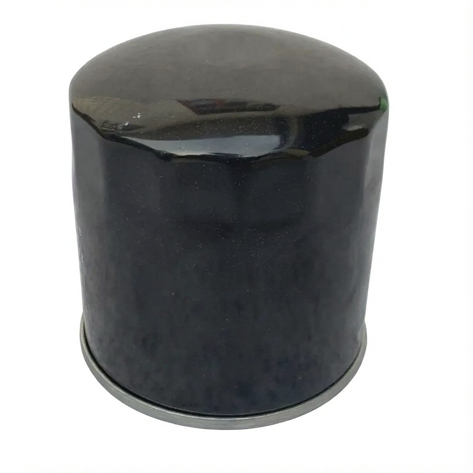
Fuel filter housings follow the same logic but ask more of the material. Petrol and diesel are picky about what they touch, so these are often drawn in stainless steel or a plated low-carbon steel that resists the fuel and the water that rides with it. We draw 304 stainless steel for corrosive service and a zinc- or tin-plated steel for the high-volume economy can; the 304 versus 316 notes for sensor housings carry over to filter bodies because the corrosion question is the same.
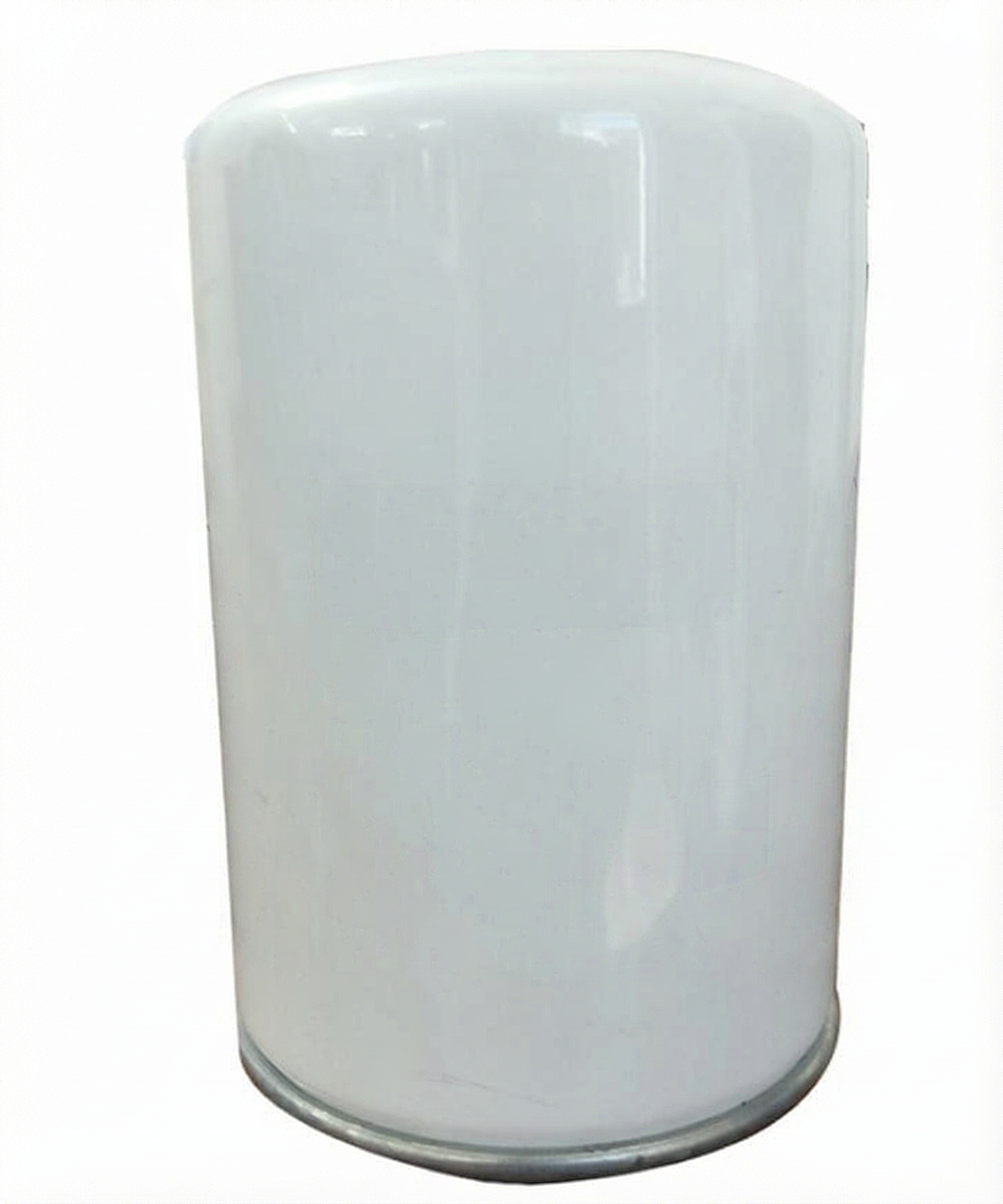
Cartridge housings skip the spin-on thread and keep the seamless shell as a permanent vessel with a separate replaceable element. The drawn part is identical in spirit — one wall, no seam — and the opening carries a flange or a bayonet instead of a nut.
Materials we draw for filter service
| Material | Where it goes | Why |
|---|---|---|
| Low-carbon steel, zinc or tin plated | High-volume spin-on oil filters | Cheap, formable, the plate resists ordinary oil |
| 304 stainless steel | Fuel filters, corrosive or food-grade service | Resists petrol, diesel and water without a coating |
| 316 stainless steel | Marine, biofuel, aggressive chemical duty | Holds up where 304 would pit |
| Aluminium (5052, 5754) | Weight-sensitive automotive and small-engine housings | Lighter shell, still drawn in one piece |
We do not publish a single wall thickness for a filter can, because the wall is a consequence of the draw. It thins near the punch radius and thickens toward the flange, so we budget roughly 10% per stage and measure the finished wall on the first article rather than quoting the incoming gauge. The limiting draw ratio reference gives the planning ceiling for each grade before a redraw has to be added.
The limits that decide the route
Depth is the first wall. We draw to 150 mm on our presses, often over two or three redraws, and we iron the wall when the print calls out a controlled thickness rather than just a starting gauge. The ironing versus redraw page separates the two passes: redraw changes the shape, ironing changes the wall.
Material flow sets the second limit. On our line we draw to a limiting ratio of 2.1–2.2 for DC04, 1.85–2.05 for 304 stainless steel and 1.80–1.95 for 5052 aluminium. Past that the shell splits at the punch radius, so we add a redraw or an anneal. A filter can is rarely near the ceiling — it is a short, wide draw — but a tall narrow housing for a fuel rail or a sensor-mounted canister can be, and that is where the planning matters.
Threads and holes are the third. We do not cut a thread into the drawn wall; the threaded boss is a pierced or welded feature at the open end, and any hole in the closed end is punched in a later station, never by the draw itself. The sensor housing case study shows the same handover between drawing and secondary operations on a part that also lives under pressure.
What we do not claim
We do not claim deep drawing removes every secondary operation. The base plate, the bypass seat, the thread and the anti-drain valve are fitted after the shell is drawn, and a fuel filter that needs a welded inlet nipple gets one. What we do claim is that the shell — the part that holds pressure and seals the media — is one seamless piece, and that is the part a welded can struggles to match.
We also do not publish leak-rate or burst-pressure figures for a filter housing we have not tested to a standard on our own line. The pressure a shell will take depends on the wall we measure, the material and the flange design, so we agree the test method with the customer before we quote a number. And we do not say 6xxx aluminium draws like 5xxx; those grades are for shallow forming with T6 applied afterwards.
Sources behind this guide
The process behaviour above sits inside work maintained outside our shop.
- ASM Handbook, Volume 14B: Metalworking — Sheet Forming — deep drawing formability, wall thinning and redraw planning.
- ASTM A240/A240M — the specification the 304 and 316 stainless steel sheet we draw is supplied against.
- ISO 9001 — the quality standard our first-article inspection and records sit under.
- Wikipedia: Deep drawing — background on the draw, redraw and ironing sequence.
How to send us a filter housing
Send the overall diameter and depth, the closed-end shape, the wall gauge, the material, the mounting type (spin-on thread, flange or bayonet) and any dimension that has to seal or seat. Tell us the service — engine oil, diesel, petrol, biofuel — because that picks the material. We will say whether the shell draws in one piece or needs a redraw, and where the thread and holes go as secondary work. Tooling is made in house, quotes come back within 24 hours, and the minimum run on new tooling is 1,000 pieces.
Frequently asked questions
Why use deep drawing instead of welding a filter can from tube and plate?
A drawn shell is one continuous piece of metal with no longitudinal seam, so there is no weld line for oil or fuel to leak through and no heat distortion of the bore. The wall thickness stays consistent because it is set by the punch, and the inside diameter repeats to ±0.05 mm. A welded can stacks the tolerances of the tube, the caps and the seams, and adds three joints where a fatigue crack can start.
Which material is used for oil and fuel filter housings?
High-volume spin-on oil filters are usually zinc- or tin-plated low-carbon steel. Fuel filters and corrosive or food-grade service move to 304 stainless steel, with 316 for marine, biofuel or aggressive chemical duty. Weight-sensitive housings are drawn in 5052 or 5754 aluminium. The material choice follows the fluid: petrol and diesel decide whether a coating is enough or the shell has to be stainless steel.
What tolerances can a deep drawn filter housing hold?
We hold ±0.05 mm on a standard tool and ±0.02 mm on an ironed wall. Depth runs to 150 mm and wall from 0.15 to 3.0 mm on our 5–500 ton presses. The dimension that repeats tightest is the inside diameter, because it is given by the punch rather than by a tube mill. Any thread, hole or seat is a secondary operation and is toleranced on its own.
Can deep drawn housings include threads, flutes and base-plate seats?
The seamless shell carries the wall, the closed end and the flange. Threads, flutes and base-plate seats are added as follow-on work: flutes are pressed in during drawing or a later station, the threaded boss is a pierced or welded feature at the open end, and the seat and holes are punched after the shell is formed. We do not cut a thread into the drawn wall itself, because that would break the seamless surface that makes the part worth drawing.
What is the minimum order and lead time for a drawn filter housing?
The minimum run on new tooling is 1,000 pieces, and tooling is made in house so the die and the first articles stay under our own control. Quotes come back within 24 hours once we have the diameter, depth, wall, material and mounting type. Lead time depends on whether the shell draws in one piece or needs redraws and secondary operations, but the tooling is the gate, not the press time.
Hydraulic filter housings in application
Beside oil and fuel spin-on canisters, the same deep-drawn shell technology is used for hydraulic filter canisters. The pictures below show finished hydraulic filter assemblies: the drawn stainless shell is the body, with the flange, clamp ring and ports added after forming. We supply the drawn shell; the assembled unit is shown here to make the end use clear.
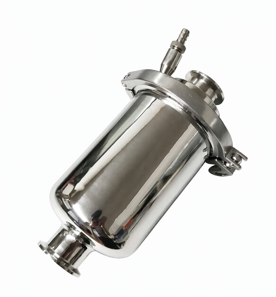
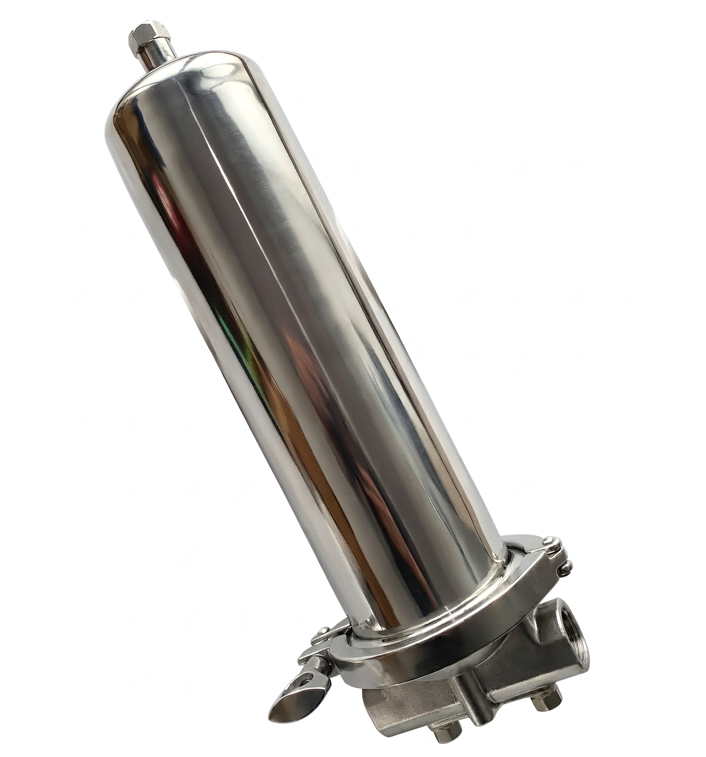
Key point: An oil or fuel filter housing is a seamless drawn shell whose closed bottom and flanged open top are formed from one blank.
Last reviewed: 2026-11-05 · Reviewed by Sam Zhang, Process Engineer