
CAPABILITY · TOOLING
Tool & Die Design, Built In-House
Dies designed in CAD, cut on our own machines, proven on our own presses — the reason our quotes and our lead times hold.
One Team Owns the Die
Every deep drawn part lives or dies by its tooling. When die design is outsourced, every engineering change becomes a negotiation between suppliers. At Aunov the die shop sits beside the press shop: our designers build the CAD model, our machines cut the steel, and our die makers prove out the tool on the same floor where your part will run. When your drawing changes, the loop is hours — not weeks.
We design and manufacture progressive dies, single-station draw dies, compound dies and engineering-sample soft tools. More than 500 sets of tooling have been built in-house over 15+ years, covering sensor housings, motor shells, valve tubes and battery cans.
Clearances, Radii and Draw Beads
Draw quality is decided in fractions of a millimetre. Tool geometry and forming limits for sheet drawing are covered in ASM Handbook, Vol. 14B. Punch-to-die clearance is set at roughly 8–12% of material thickness depending on alloy and finish requirement; punch and die radii are sized to let metal flow without tearing; draw beads and blank-holder pressure are tuned to control material flow into the cup. For progressive tools, the strip layout balances station load so the press runs stable at speed.
Because we cut our own steel, we can afford to iterate. A tool that draws beautifully in simulation but opens up wrinkles on the press is re-machined and re-proven here — the customer sees finished samples, not excuses.
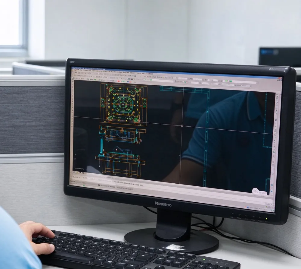
How a Draw Die Is Designed
Tool design starts from the finished part and works backwards. We add the trim allowances to the final geometry, then reverse the forming sequence one operation at a time until we reach the flat blank. Each step backwards adds material that the next step will consume, so the calculated blank is larger than the net surface area of the part. Getting that sequence right before any steel is cut is what separates a die that runs for a million strokes from one that splits parts on day one.
- Blank development. Surface area is calculated and then corrected for wall thinning and for metal trimmed from the flange.
- Draw radii. Punch nose radius is normally four to ten times material thickness, die entry radius six to twelve times. Too small a die radius restricts flow and splits the part; too large a radius releases the blankholder early and wrinkles.
- Clearance. Set at material thickness plus 7 to 20 percent per side, tighter for ironing and wider on the first draw where the wall thickens.
- Blankholder force. Sized to hold the flange flat without tearing the wall. On stainless steel this is the parameter most often adjusted during tryout.
- Venting. Draw cavities are vented so trapped air does not distort the part on the return stroke.
We simulate the sequence before cutting steel. Forming analysis flags thinning hot spots, predicts wrinkle zones in the flange and shows whether a corner radius on a rectangular shell is achievable at the specified thickness. It is a guide rather than a guarantee, so the first article is always proven on the press before anything is hardened. On a part such as our steel deep drawn cubic box with dual side holes, the analysis shows where corner material piles up and how much trim to leave around the flange. The same forming studies also scope our broader metal stamping and forming capabilities.
Design output reaches the toolroom as a full package: die layout, sectional views, and a parts list giving steel specification and target hardness for every component. Each insert is dimensioned so it can be replaced without reworking the die shoe, which keeps a high volume tool economical across its life.
Tooling Types and When We Use Them
The tooling configuration follows quantity, geometry and material. A prototype run of two hundred parts and a production run of two million justify different tools, and quoting the wrong one either inflates the unit price or yields a tool that wears out early.
- Single station draw dies. One operation per stroke, hand or robot loaded. Used for prototypes, small batches and parts needing an intermediate anneal. Cheapest tool, highest piece cost.
- Progressive dies. The blank rides a carrier strip through piercing, drawing, redrawing, trimming and forming stations in one die set. Used above roughly fifty thousand pieces a year.
- Transfer dies. The part is separated at the first station and moved mechanically between stations. Chosen for deep parts, for round blanks, or where a carrier strip is impractical.
- Compound dies. Two or more actions in one station, used where concentricity between a pierced hole and a drawn shell must be held tightly.
- Ironing and redraw tooling. Thins and lengthens the wall deliberately, most often on tube shells needing a uniform wall and a smooth bore.
Tool steel selection follows the work material. Drawing stainless steel work hardens the surface and generates heat, so inserts run in high speed or powder metallurgy grades such as M2, ASP23 or Vanadis at 60 to 64 HRC, usually nitrided or PVD coated. Aluminium and copper are less abrasive, so D2 or A2 at 58 to 62 HRC with a polished die face is normally enough. Carbide is reserved for ironing rings and for long runs where wall thickness drift cannot be tolerated.
Valve work gets dedicated multi stage tooling with a guided punch and a close fitting stripper bushing, because concentricity between bore and outside diameter drives solenoid performance. Our stainless steel deep drawn solenoid valve tube runs on a tool of that type, with the bore checked by plug gauge at set intervals.
Tool Life, Maintenance and Storage
Tool life is counted in strokes, not in calendar time, and we log it. Each die set carries an identification plate and a stroke counter, and the maintenance interval is set from the material and the severity of the draw rather than a fixed schedule. A progressive die drawing soft aluminium from 1.0 mm strip may run eight hundred thousand strokes between regrinds; the same tool on a severe stainless steel reduction may need attention at one hundred and fifty thousand.
- Preventive work between runs covers punch to die alignment, blankholder parallelism, stripper travel and vent condition.
- Every regrind is recorded, with the amount removed and the shim added to restore shut height.
- Tools are cleaned, dried, coated with rust preventive and stored with the shut height blocked open so springs are not left compressed.
Tools belong to the customer. They are held in a controlled area indexed by part and die number, and are not scrapped or modified without written instruction. Before a stored tool returns to the press after a long gap we run a verification piece and check critical dimensions against the last recorded inspection. That is also why tooling is a one time investment rather than a recurring cost, an argument set out in our note on how deep drawn parts reduce manufacturing costs. Secondary operations, such as the oval cut ends on copper drawn tubes, get their own fixtures rather than being folded into the draw die.
Frequently Asked Questions
How long does it take to design and build a draw die?
A straightforward single stage die is typically four to six weeks from design release to first article, and a multi station progressive or transfer tool is eight to fourteen weeks. The range depends on how much tryout the geometry needs and on whether special tool steel or coating has to be sourced.
Who owns the tooling?
The customer owns it. We hold it, maintain it, keep the regrind and repair records and run it only for that customer’s parts. It is not scrapped or altered without written instruction, and it can be transferred on request.
Can an existing tool be modified for a design change?
Often yes, depending on the change. A deeper draw or a smaller corner radius usually needs new draw stations, while a relocated hole or a revised flange trim can normally be handled with new pierce and trim sections in the existing die shoe. We assess the change against the current tool drawing before quoting.
How many strokes will a draw die last?
Life depends on the material, the severity of the reduction and the tool steel. Progressive tools on soft aluminium commonly run several hundred thousand strokes between regrinds, while severe stainless steel draws may need attention at around one hundred and fifty thousand. We set the interval from the logged stroke count for each tool.
Do you simulate before building tooling?
Yes. Forming simulation is run on every new draw sequence to predict thinning, wrinkling and springback. It reduces but does not remove the need for tryout, so the first article is still proven on the press and the tool is adjusted before production starts.
Continue through the capability tour: the deep drawing process and stamping & forming capacity.
Talk To Our Engineers
Send your drawing to [email protected] — material advice, tooling plan and a per-piece price within 24 hours.