
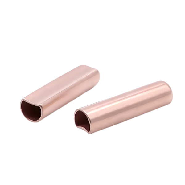
The Copper Drawn Tubes with Oval Cut Ends starts life as a flat circular blank and finishes as a seamless shell whose end section is deliberately oval – a geometry that shows up in sensor probes, valve bodies and heat-transfer assemblies where a round tube must marry into an oval port. This page walks through how the oval is formed, what it does to the process plan, and the checks that decide whether a batch ships.
From round drawn tube to an oval mouth: the forming sequence
The tube is first drawn round, in staged passes over a plug through successive die rings, because a round cross-section is the only shape that draws evenly in every direction. Only after the round shell has reached its final length and wall gauge do we ovalise the end section, in a dedicated calibration hit between profiled dies. The sequence matters: ovalising first and drawing afterwards would put the oval through every subsequent die ring and destroy it.
- The ovalising dies squeeze the end section between two matched profiles, and the transition from round to oval happens over a controlled land – typically 8 to 15 mm, set by the die entry angle rather than left to springback.
- Copper springs back far less than steel, so the dies are cut only marginally oversize on the minor axis – roughly 2% compensation against the target, compared with 4-6% we would allow on SPCC for the same reduction.
- The unsupported length beyond the dies is kept under one tube diameter; any longer and the free section ribs or folds instead of flowing smoothly into the oval.
Wall redistribution is the physical story here: metal leaves the minor-axis sides and gathers at the major-axis extremes, so the finished oval carries a wall that varies around the perimeter by 10-15%. We record that variation on the first-article report at named angular positions, because a downstream brazing or crimping operation needs to know where the wall is thinnest before it applies force.
Annealing strategy for copper in a two-temper part
This part is unusual because it legitimately needs two different material conditions in one length. The drawn body wants ductility gone – a half-hard temper that holds its shape in handling – while the oval end wants maximum formability at the moment the dies close. Copper work-hardens quickly; by the final drawing pass the shell has lost most of its elongation, and ovalising it as-is invites cracking at the major-axis extremes.
- We plan an intermediate anneal between drawing stages at around 400 °C in a bright anneal atmosphere, which resets the grain without oxidising the bore that no pickling step can reach cleanly afterwards.
- The ovalising hit then runs on material in the correct condition, and the final temper is set by a closing anneal whose cycle is archived against the part number – soft for a brazed-in end, half-hard where the tube end carries a load.
- Grain size is watched, not assumed: we target the 0.02-0.05 mm range, because coarse-grain copper orange-peels in the dies and fine-grain copper cracks at the transition radius.
The temper call-out on your print is the one line item that changes the whole anneal schedule, so we quote it explicitly: a part specified dead-soft for a crush seal at the oval end is a different manufacturing plan – and a different price – from the same geometry in half-hard.
Where the dimensions actually sit on an oval end
On the round body, the named measurements are conventional drawn-tube numbers: ID, OD and their concentricity held together to ±0.1 mm as-drawn, with wall thickness documented at the thinnest section. The oval mouth changes the metrology plan. There is no single “diameter” to gauge any more – the controlling dimensions become the major axis, the minor axis, and the angular orientation of the oval plane relative to any feature further down the tube.
- The major and minor axes are set by the dies, so they hold close to as-drawn tolerance; where an oval port must seal or locate, the oval land is machined afterwards and holds ±0.03 mm.
- The oval plane orientation is the dimension customers forget to put on the print and then discover in assembly – a 90° rotation error turns a drop-in fit into a no-go. We gauge it at first article and flag it as a drawing-review question when the print is silent.
- Transition length – the distance from full round to full oval – is controlled because it decides how much tube can engage the mating port before the geometry changes.
Concentricity between the round bore and the oval ends is measured as runout of the round section against the oval centre, and it is the number that predicts vibration in the finished assembly rather than any single-axis diameter.
Cutting the oval mouth without burying debris in the bore
End cutting happens after ovalising, and the cutting method is chosen against the part’s duty, not by habit. Copper machines beautifully but it smears: a dull tool leaves a burr rolled into the bore that a pressure test will pass and a flow test will not. For fluid-duty parts we treat the cut end as a functional feature in its own right.
- Short tubes are faced on the CNC turning centres with a sharp high-rake insert at high surface speed, which shears the copper cleanly and leaves a burr height we hold under 0.05 mm before any deburring step.
- Long slender tubes are supported at the cut point, because an unsupported oval section will chatter and the cut end loses its flatness – a defect invisible to a calliper check but obvious when the tube seats against a shoulder.
- After cutting, bores are flushed and inspected under magnification; copper swarf is soft, but in a valve or sensor it is still a loose particle waiting to lodge in the first narrow passage downstream.
Where the print calls for a chamfer or radius at the oval mouth, it is machined, not filed into existence by an operator – the difference shows up as repeatability: part 400 looks like part 4 because both came off the same numbered program.
Why seamless drawn stock earns its place at the oval
Welded tube is the obvious alternative for a copper tube with a formed end, and it is cheaper per metre at the mill – but the weld seam is precisely where an ovalising hit concentrates strain. The seam and its heat-affected zone sit through the wall thickness, and when the dies close on the end section, that locally stiff, locally brittle band takes a different strain path from the parent metal. The result at the major-axis extreme is a classic failure: a longitudinal split that starts inside the transition zone, where it cannot be seen in a visual check.
- A drawn shell has no seam, so the oval forms symmetrically and the wall variation around the perimeter follows the die geometry rather than the weld’s temper.
- For sensor probes the continuity argument is stronger still: a seamless copper wall conducts heat and current without interruption, which matters when the tube is the thermal path the sensor depends on.
- The failure mode we design against shifts from “will the seam crack” to “is the wall distribution documented” – a question with a measurable answer.
How we verify an oval-end copper tube before it ships
Every batch runs the same acceptance sequence, written per part number and archived with the process record:
- First article on the CMM in the climate-controlled room: ID, OD and concentricity on the round section, then major axis, minor axis, oval-plane orientation and transition length on the formed end, all against your print.
- Wall thickness mapped at the documented thinnest positions – round section and both major-axis extremes – with the numbers recorded so the brazing or crimping step downstream knows what it is loading.
- End condition checks: cut-face squareness to the tube axis, burr height under magnification against the 0.05 mm limit, and bore cleanliness verified before the parts are packed.
- Material and temper evidence: mill certificate per heat plus the anneal cycle record, tied to the drawing revision that produced the batch.
- Production gauging back to the signed first article on the agreed sampling plan – reorders are judged against the archived sample, not against memory.
This part belongs to our Deep Drawn Tubes & Sleeves range. The deep drawn tubes & sleeves pages collect the process notes, common materials and inspection points behind every product in the family.
Specifications
| Item | Copper Drawn Tubes with Oval Cut Ends |
|---|---|
| Brand | AUNOV |
| Designing | A drawing file or a physical sample starts the review, a manufacturability review comes back with the quotation. |
| Tooling | Every die designed and built in our toolroom, stored under your part number. |
| Samples | First articles go out with a dimensional report and material certificate. |
| Materials | Copper leads the stock list for this part, alongside carbon steel (SPCC / DC01), 304 / 316 stainless steel, aluminium and brass, per the drawing. |
| Surface finish | Finishes on offer: plating, e-coat, powder coating, anodising or passivation, set by your print. |
| Processing | Progressive deep draw stages with in-line annealing as the draw ratio demands, then pierced and CNC-machined in house. |
| Equipment | Our press floor runs 5-250 T mechanical and 250-500 T hydraulic presses, CNC cells plus a temperature-controlled CMM room. |
| Tolerance | As-drawn tolerance +/-0.1 mm, machined features held to +/-0.03 mm. |
| Delivery terms | Standard terms FOB, DDP offered to EU and US, payment T/T or L/C, D/P for repeat accounts, call-off schedules and blanket orders supported. |
Related Products


Request a Quote for This Part
Send a drawing or sketch — get material advice, tooling cost and a per-piece price within 24 hours (working days).