
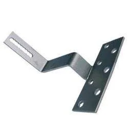
Why a bracket has more holes than it needs
A multi-hole stamped mounting bracket is easy to make and easy to get wrong, because every hole looks trivial and each one adds a way for the joint to fail. Two failure modes account for most of the trouble, and neither is the failure mode people check for. The first is a hole that is in the wrong place – position error against a mating part’s pattern. The second is a hole that is the right size and in the right place and still leaks, because it sits outside the wetted envelope of the joint. Everything else – the drawing detail, the tolerance scheme, the inspection plan – follows from taking those two seriously.
We blank and progressively form these on automated lines, with secondary tapping, bending and finishing, on 5-250 T mechanical presses with dedicated dies, backed by CNC turning centres and a climate-controlled inspection room. Bend positions hold to +/-0.05 mm and the blank outline to +/-0.1 mm, with finer bands confirmed from capability data before quoting. Finish thickness and adhesion are checked on the first article, and mill certificates and heat numbers accompany it.
The pattern is a tolerance problem before it is a strength problem
Start with the positions, because that is where multi-hole parts actually fail. A pattern with four or six holes is not four or six independent tolerances – it is a positional relationship, and the relationship can be specified and controlled in ways the individual positions cannot.
- True position. The correct GD&T control for a hole pattern. It says nothing about the size tolerance of any individual hole, so a hole can be made to size by the drill and still located by the pattern control. Without it, each hole gets its own positional tolerance and the errors accumulate into a pattern that can drift.
- A common datum. All the holes are located from one datum, so the pattern cannot rotate relative to its own mounting face. This is the single most valuable call on the drawing.
- Pattern position as one dimension. Stating the basic dimensions for the pattern, so the intent survives the drawing exchange, rather than a chain of coordinate dimensions that everyone interprets differently.
The stack the pattern has to survive is the sum of the bracket’s own pattern error, the mating part’s pattern error, and any clearance in the fasteners. On a multi-hole bracket the third term is usually the largest and it is the one that gets ignored – a 6.6 mm hole for an M6 fastener gives roughly 0.7 mm of diametral float, which buys a great deal of stack for free, while a close-fit hole buys none at all. Where the joint is meant to locate precisely, the extra holes should be clearance holes and one hole, or a dowel, should do the locating.
Which holes are actually load-bearing
A multi-hole bracket often carries more fasteners than the load needs, and that is not automatically a good thing. Each additional hole is a potential leak path, a potential stress concentration, and a potential site for corrosion to start. The useful question is which holes actually do structural work.
- A bolted joint in shear. The load is carried by friction between the faces, which means the preload of every bolt matters and the joint’s slip resistance is the design number. More bolts at the same total preload does not help much, because the limiting factor becomes the joint’s stiffness and its ability to stay clamped.
- A joint in bearing. If the joint separates under load, the fastener is in bearing against the hole wall and hole diameter becomes a real structural dimension, not just a clearance. More bolts genuinely reduce the bearing load per bolt, and larger holes make it worse.
- Hardware in tension. On a thin bracket, the washer bearing area governs, and the bracket can tear around a hole or crush under a head. This is where hole spacing rules come from.
Which of these applies should be written on the drawing, because it determines whether the holes are clearance holes, close-fit holes, or slotted, and it determines how many you actually need. DFM feedback accompanies the quotation here, so the question gets raised before the die is cut – which is the only cheap time to ask it.
Edge distance, form and the tearing limit
Two geometry rules decide whether a multi-hole bracket tears around a hole, and both are about how much material is left between features:
- Edge distance. Distance from hole centre to the edge of the part, conventionally at least twice the hole diameter. Below that, the material ahead of the hole cannot develop the full bearing stress and the bracket tears. Above it, the section can develop its full strength.
- Material between adjacent holes. The web between two holes has to carry the load without a free edge on either side, and a thin web also has a stress concentration at each hole. A web narrower than about one hole diameter is where a multi-hole bracket fails first, and the failure is a crack that runs between two holes.
A lanced tab or a formed dimple is the standard fix where the pattern is tight. The tab spreads the load into a wider area of material without needing more space, and it does it in the same progressive die. It costs a small amount of extra material forming and, on some patterns, it is the difference between a design that works and one that tears.
Coating and the hole that never dries
This is the failure that gets discovered after a warranty cycle rather than in the lab. A bracket with an exposed mounting face has holes through that face, and every hole is a discontinuity in the coating. Paint spray systems coat a face evenly; they do not reliably coat the inside of a hole and the cylindrical wall behind the washer. The result is a bare steel edge inside a coated joint, holding a crevice where water and salt sit.
Three mitigations, and which applies depends on the service:
- Coat after assembly of the bracket to the mating part. Not usually practical for a supplied component.
- Specify the coating system for crevice resistance. Zinc flake systems such as zinc-aluminium are markedly better in a crevice than conventional electroplating, because they are sacrificial and they pack a corrosion-resistant flake into the gap.
- Reduce the number of exposed holes. A bracket designed to use four fasteners instead of six has four crevices instead of six, and this is a design decision that costs nothing at the assembly line.
Stainless steel removes the corrosion mechanism entirely rather than managing it, at the cost of galling at the threads and a higher price. Where the joint is disassembled repeatedly, galling on stainless steel fasteners is a real service problem and a nylon patch insert or a specified anti-galling coating is the standard answer.
Hole size, tapping and the secondary operations
Where a hole carries a thread rather than a bolt, the drawing has to say how the thread is made and what it is made into. The route on this part type is blanking and progressive forming followed by secondary tapping, bending and finishing – the tapping is a separate operation, and it has consequences:
- Tap size and thread engagement. A thread in sheet needs more engagement than the same thread in a solid. Below roughly one diameter of engagement the thread strips easily; above about 1.5 diameters it holds. This is why drawn parts get tapped holes only after a drawn or formed boss has been provided.
- Tap hole size. A hole tapped M6 is drilled undersize for M6. If the drawing says M6 and says nothing about the hole, the tap may not fit, and the hole itself is not a tolerance the customer normally inspects.
- Thread class and gauge. Specify the class and whether the thread is gauged. An ungaugeed thread is not a specification.
- Hole position versus tapping. A tapping operation follows the drilled hole, so the position error of the tap is the position error of the drill. There is no second chance at a tapped feature, which is why tapped holes are pierced in the flat, in the same station as the outline wherever the geometry allows.
Commercial terms and how to get a tight pattern quoted
Stock runs to carbon steel, 304 and 316 stainless steel, aluminium and brass. Progressive and drawing dies are designed and built in house, so the die charge appears as its own quotation line and is refundable against agreed volumes. Finish thickness and adhesion are checked on the first article, and dimensional reporting accompanies it.
Three things on the drawing make a multi-hole bracket cheaper to make and easier to guarantee, and they are worth the effort to specify:
- Locate every hole in one datum with true position. It costs nothing on the drawing and it removes a whole class of assembly problem.
- Say which holes are clearance, which locate, and which are unused in some variants. A pattern with a spare hole for a future variant is normal, but an unused hole through a sealed face is not.
- State the mating part’s pattern, or state the joint’s functional requirement. If we know what the pattern has to mate with, the tolerance scheme can be built to make that joint work. If we do not, the default is a general scheme that will not fit.
Send drawings in PDF, DWG, STEP or IGS, or send a sample to be measured, and the same drawing is used for every repeat order.
Parts like this one sit under the Custom Metal Stamping Parts range, whose overview page gathers the tooling logic, finishing options and tolerance notes shared across the family.
Where this part is used
Multi-hole stamped mounting brackets turn up wherever something has to be fixed down at more than two points: electrical enclosures and control cabinets, machine guards, motor and pump mounts, junction boxes, and the frames that carry instrumentation. Each hole looks trivial and each one adds a way for the joint to fail, which is why the failures that occur are rarely the ones people check for – a hole in the wrong place, or a hole that is correctly placed and correctly sized and still leaks.
The second failure mode is the one worth understanding first. A hole sitting outside the wetted envelope of a joint is perfectly accurate and perfectly placed and still lets water or dust in, because the seal only works over the land between the holes. That is why on a multi-hole part the pattern geometry – hole positions, edge distances, and the flat area between them – is a sealing and structural question before it is a dimensional one.
What we need to quote it
Send the hole pattern with the positions dimensioned from a common datum, and tell us which holes are load-bearing rather than fixing points. Give us the edge distance from the outermost hole to the part edge, because that is the tearing limit. If the part seals against something, tell us what seals – gasket, sealant, or a lapped joint – and we will check the flat land between the holes rather than just the hole positions. Material grade and thickness matter too, since they set the forming and the coating.
Specifications
| Item | Multi-Hole Stamped Mounting Bracket |
|---|---|
| Brand | AUNOV |
| Designing | DFM feedback accompanies the quotation, so surprises are caught before the die is cut. |
| Tooling | Progressive and drawing dies are designed and built in house, so the die charge appears as its own quotation line, and the charge is refundable against agreed volumes. |
| Samples | Samples are issued for approval before the run, and production starts only after written sign-off. |
| Materials | Stock runs to carbon steel, 304 / 316 stainless steel, aluminium and brass; mill certificates and heat numbers accompany the first article. |
| Surface finish | Plating, coating or polishing to suit the drawing; finish thickness and adhesion checked on the first article. |
| Processing | Blanking and progressive forming on automated lines, then secondary tapping, bending and finishing. |
| Equipment | Press shop with 5-250 T mechanical presses and dedicated dies, backed by CNC turning centres and a climate-controlled inspection room. |
| Tolerance | +/-0.05 mm on bend positions, +/-0.1 mm on blank outline; finer bands confirmed from capability data before quoting. |
| Delivery terms | Delivery quoted per Incoterms 2020 – FOB, CIF or DDP – by sea or air, to your address. |
Related Products


Request a Quote for This Part
Send a drawing or sketch — get material advice, tooling cost and a per-piece price within 24 hours (working days).