
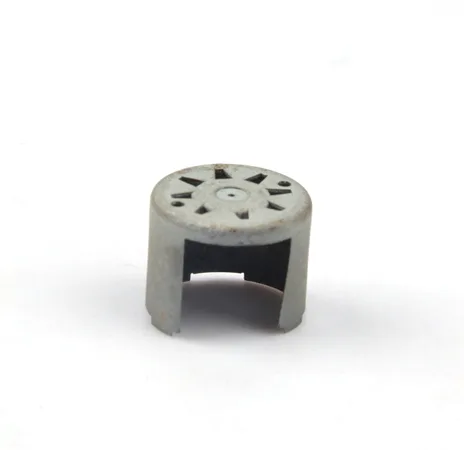
A deep drawn enclosure is a housing drawn as one piece — floor, walls and often the flange in a single shell, with no welded corners to seal and no folded seams to corrode. For electronics, sensors and instruments, that one-piece construction is the point: it turns the housing itself into the dust seal, the moisture barrier and, when the wall is metal, the EMI shield. Aunov Tech draws enclosures to customer print in steel, stainless steel and aluminium, with secondary machining, finishing and CMM inspection on the same floor.
Why enclosures are drawn rather than folded
A folded sheet-metal box needs four corners — welded, seamed or riveted — and every one of them is a path for water, dust and electromagnetic leakage. A drawn enclosure has none. The trade is tooling: an enclosure die is dedicated geometry, which is why drawing wins once volumes justify it. The decision usually looks like this:
- Drawn wins when: volumes are ongoing, ingress or EMC performance matters, and the geometry is round or gently rectangular with generous radii.
- Folded wins when: volumes are low, the box is large and flat-sided, or the design changes often enough that die changes would eat the saving.
If you are between the two, custom metal stamping and laser-and-form routes can carry early builds until the volume proves a draw die — worth asking at RFQ rather than assuming.
What a drawing must get right for an enclosure
Enclosure prints fail feasibility on the same handful of items, so these are checked before any price is issued:
| Design item | Practical rule | Why |
|---|---|---|
| Depth vs diameter | Up to ~2:1 in one draw; deeper shells redrawn with interstage annealing | Beyond that, the wall thins past control or the flange wrinkles |
| Corners (rectangular shells) | Inside radius ≥ 4× sheet thickness | Tighter corners split; sharp features belong on machined bosses |
| Mating face | Flatness called and CMM-verified | The gasket face is where springback shows first |
| Openings & bosses | Pierced/machined after forming | Forming moves pre-pierced features; the sequence holds positions |
| Wall thickness | Held to print, thinning monitored at the top radius | The wall is the seal and the shield — its minimum matters |
Ingress and EMC: what the process contributes
A drawn wall is continuous, but “continuous” still has to be earned at the details:
- Gasket seats. The flange or rim that carries the gasket is formed to print and its flatness measured on the first article — a wavy seat defeats any gasket, whatever its IP rating.
- Seam-free through the wall. No weld beads to grind, no coating breaks at corners; e-coat reaches drawn corners uniformly where spray cannot, which is why it is the usual primer under powder on enclosure work.
- EMC continuity. A one-piece metal wall is a natural shield; the places to manage are the unavoidable openings — cable entries and lids — where conductive gaskets or machined seating faces close the loop. Machining of those faces happens in-house, so the seat that closes the shield is held to the print that designed it.
- Drains and breathers. Vent or drain features are pierced after forming, positioned so they work with the orientation the enclosure actually sees in service — worth stating at RFQ, not discovering in the field.
Materials for enclosure duty
Stock runs to carbon steel SPCC / DC01, 304 and 316 stainless steel, aluminium and brass; special grades are sourced to the drawing when volumes justify. The service shortlist:
- SPCC / DC01 + zinc or e-coat + powder — the standard indoor/outdoor route; least material cost, needs the finish to survive.
- 304 stainless steel + passivation — washdown and food-adjacent equipment; no paint to chip, corners stay clean.
- 316 stainless steel — coastal, chemical or salt-spray duty.
- Aluminium + anodising — weight-sensitive instruments and thermal paths; draws well, dents more easily, so handling is part of the design conversation.
Grade reasoning in depth is on material selection & sourcing; the finish menu and how it is held between batches is on the deep drawn covers guide.
Tolerances and inspection
Standard control is ±0.05 mm to ±0.1 mm across the part, wall thickness held to print; finer bands are confirmed from capability data before quoting rather than promised blind. First-article inspection on the CMM carries seal-face finish and cavity depth; production batches follow the sampling plan agreed at approval under the ISO 9001 system. Torque, leak or pressure testing is built into the quality plan where the assembly calls for it, with results in the batch file. Tooling and setup records are stored against the part number, so nothing depends on someone remembering — first article, drawing revision and material cert travel with each batch.
From sample to volume
Samples are produced on production tooling, so what you approve is what you get. Reverse-engineering is supported: a physical sample is measured into a controlled drawing, which then becomes the master for every repeat order. Die design and wire-cut EDM are in-house (see tool & die design), the die charge is its own quotation line, and first-article timing is measured from the tooling start date. Reorders are repeats of an approved process, not new projects.
Enclosure work across this site
Worked examples of the family: junction box enclosure with socket panel, aluminium enclosure with rounded corners, painted enclosure box with flanges, aluminium smoke detector cover, and the cans, caps and sleeves family for container-form variants. Sensor- and motor-specific shells are under sensor housings and automotive motor components.
Requesting a quotation
Send the 2D/3D drawing (PDF, DWG, STEP, IGS) — or the sample if that is what exists — with material, finish, annual volume and ingress or EMC requirements. The quotation returns with a manufacturability review: draw ratio, corner radii, flatness and tolerance bands checked against what the die will hold, and the tooling cost shown as its own line. Route it through the quote request page.
Frequently asked questions
Can a drawn enclosure reach an IP-rated seal?
The drawn shell supplies the continuous wall; the rating is earned at the gasket seat and lid interface, which are formed and machined to print and verified for flatness at first article. State the target IP at RFQ so the seat is designed for it.
Is a drawn enclosure actually better for EMC than a folded box?
The one-piece wall has no seam leakage paths; performance is then set by openings and lid joints, where conductive gaskets and machined faces close the loop. For shielded electronics the difference is real, not theoretical.
How deep can the enclosure be in one draw?
About 2:1 depth to diameter depending on grade; deeper designs are redrawn in stages with interstage annealing. The feasibility review at quotation will show the stages and their effect on price.
Can you work from a sample instead of a drawing?
Yes — the sample is reverse-measured into a controlled drawing, you approve the drawing, and every later batch builds from it. The sample stops being the reference; the drawing does.
| Item | Deep drawn enclosure |
|---|---|
| Brand | AUNOV |
| Designing | Made to your 2D/3D drawings (PDF, DWG, STEP, IGS) — samples are reverse-measured into a controlled drawing kept as the master. |
| Tooling | In-house die design, wire-cut EDM and maintenance; die charge as its own quotation line; first-article timing from tooling start. |
| Samples | Produced on production tooling — measured, reported, approved before volume. |
| Materials | Carbon steel (SPCC / DC01), 304 / 316 stainless steel, aluminium, brass; special grades sourced to drawing when volumes justify. |
| Surface finish | Zinc / nickel / chrome plating, e-coat, powder coating, anodising, passivation; alternatives quoted with the quotation, samples approved in writing. |
| Processing | Progressive drawing through several stages, annealed between draws, then trim and pierce; every stage logged against your part number. |
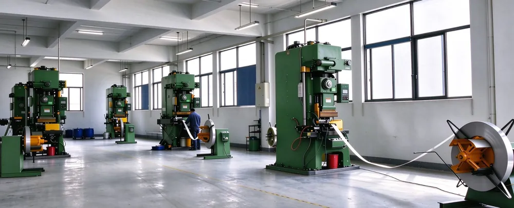
| Equipment | 5–250 T mechanical presses, 250–500 T hydraulic presses, in-line annealing furnaces; secondary ops on CNC turning centres; inspection on the CMM. |
| Tolerance | ±0.05 mm to ±0.1 mm across the part, wall thickness held to print; finer bands confirmed from capability data before quoting. |
| Delivery terms | FOB unless DDP preferred; T/T or L/C; freight quoted to destination. |
Related Products



Request a Quote for This Part
Send a drawing or sketch — get material advice, tooling cost and a per-piece price within 24 hours (working days).