
16 Types of Deep Drawing Processes

16 Types of Deep Drawing Processes
A drawn part is not made by one operation. It is made by a route — and the route decides wall thickness, tool life, scrap rate and the price you pay.
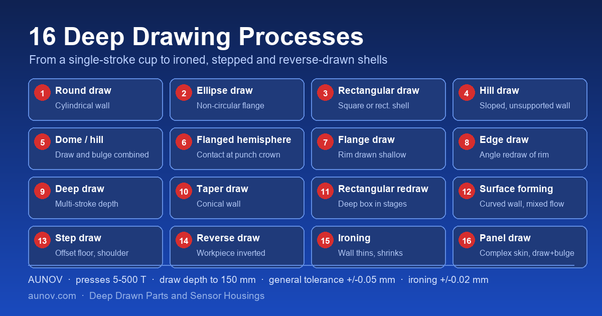
The 16 routes at a glance. Which one applies depends on the geometry of your part, not on the name of the part. Measured limits behind these routes: 5–500 ton presses, 150 mm draw depth, ±0.05 mm general tolerance and ±0.02 mm on ironed walls.
Why buyers care about the route
Two suppliers can quote the same drawing at very different prices and both be right. One is drawing a shallow cylindrical cup in a single stroke on a 60-tonne press. The other is redrawing it three times with an intermediate anneal, trimming the flange afterwards and running ironing passes on the wall. The steel cost is nearly identical; the process route is not.
Getting the route right before tooling is cut is the cheapest engineering decision you will make on a deep drawn part. Every extra stroke adds a die set, a transfer, a chance of wall misalignment and a scrap risk at the punch radius. It also changes the price band the part lands in.
There are two separate questions hiding inside “how hard is this part to draw”. The first is how difficult the geometry is, which we grade as simple, average and difficult geometries. The second, covered here, is which forming operation actually builds the shape. Both matter, and they are not the same list.
Family one — first-stroke shapes
Six operations produce the complete wall shape in one pull. They are the fastest routes and the ones with the highest yield.
1Round drawing
The baseline. A flat blank is pulled into a die cavity to form a straight cylindrical wall with a flat bottom and a flat flange. Because the wall is axisymmetric, the same amount of metal travels the same distance in every direction around the circumference, which is why this route gives the most predictable wall thickness of all sixteen.
Blank size decides the outcome in both directions. Too much flange metal and the wall wrinkles as the material has nowhere to go; too little and the wall thins hard at the punch radius and splits. Our measured limiting draw ratios — 2.1–2.2 for DC04, 1.85–2.05 for 304 stainless steel and 1.80–1.95 for 5052 aluminium — tell you the largest blank that a single stroke will accept without splitting.
2Ellipse drawing
The same principle with an oval contour. The flange still draws, but the deformation no longer travels evenly around the perimeter. Where the contour curves tighter, the metal resists more and stretches further; where the radius opens out, it stretches less. That difference is the whole engineering story of an elliptical shell.
We see this route in oval lens barrels, oval mounting flanges and elliptical sensor bodies where a circular blank would waste material. The tool needs a shaped blank outline rather than a disc, so blank development is done per geometry rather than per size.
3Rectangular drawing
A low rectangular box pulled in one stroke. The wall on the flat sides barely moves; the corners must pull harder because they carry more stretch resistance than a straight edge. The corner radius therefore sees the highest strain in the whole part, which is exactly where splits start when the radius is too tight.
Most splits reported to us on rectangular shells start at a corner, not on a wall. The fix is rarely a heavier press; it is a larger corner radius, a slightly larger blank and a blank holder force that lets the corners feed. If the box has to be deep as well as rectangular, it stops being this route and becomes a redraw route instead.
4Hill drawing
The wall slopes. During the stroke the sloped section hangs unsupported above the die and only touches down at the end of the stroke, so the metal is being formed in a partly free state. That changes both the load path and the way the wall thins.
Hill forming is used where a drawn wall needs to become a cone or an embossed slope — stepped-looking covers, tapered collars and raised shoulders. It is less forgiving than a flat wall because the unsupported section has no die support when it thins most.
5Dome and hill forming
Here the blank does two things at once. The outer flange draws as it would in a normal cup while the centre is pushed out by the punch, so the material in the centre bulges while the flange draws. It is a compound operation rather than a simple draw.
That combination shows up in covers, end caps and dome-topped housings. Because the strain state is mixed, wall thickness ends up uneven between the drawn flange zone and the bulged dome, and the plan has to be checked per zone rather than by an average number.
6Flanged hemisphere drawing
A spherical shell with a flange at the rim. The blank touches the punch only at the crown of the sphere, so most of the blank is momentarily free before it is drawn in. Material flow is therefore controlled from a small contact zone, which is why this route is one of the least forgiving of the sixteen.
Parts like pressure caps and spherical sensor bodies use it. We plan the blank and the draw ratio around the crown contact area rather than the nominal diameter, because that is where the metal is actually stretched.
Family two — rim and flange work
Two operations modify the edge of a part that has already been drawn.
7Flange drawing
A shallow draw applied only to the flange region of an existing part. Because the flange is pulled inward and compressed around its circumference, it behaves more like compression flanging than like drawing, and the failure mode changes with it. Tangential compression in a flange buckles, so the limit here is compression wrinkling rather than tensile tearing.
This is how a finished shell gets a mounting lip or a sealing rim. Holding that rim flat and crack-free needs a dedicated flange die with a well-controlled closing radius, not just a reshaped punch.
8Edge drawing
An angular redraw of the flange of a previously drawn part, typically turning a flat rim into a 90-degree or angled edge for a snap fit or a weld seam. The material has already been worked once, so it arrives at this operation partly hardened and less forgiving.
Edge drawing on 304 stainless steel and on 5052 aluminium both need the previous stage to have been annealed or formed in a single gentle stroke, otherwise the edge tears instead of bending cleanly.
Family three — building depth
Three operations go past what a single stroke can do. This is where the cost of a deep drawn part comes from.
9Deep drawing
When the part is deeper than the single-draw limit allows, it is drawn in several strokes with the wall re-centred between them. Each stage reduces the diameter and increases the depth. The wall must be located precisely in the draw ring at every station, because a wall that wanders off centre produces a part that is thin on one side and thick on the other.
For stainless steel, intermediate annealing between stages is normal, since the material work-hardens fast and the limiting draw ratio drops sharply as it does. For 5xxx aluminium alloys the material stays far more forgiving through the same sequence, which is one reason aluminium and stainless steel parts of identical geometry do not cost the same to make.
10Taper drawing
A deep cone, typically with a depth-to-diameter ratio above 0.8 and a half angle between 10 and 30 degrees. Because the wall is steep, only a small contact area carries the forming force, so the metal stretches hard right where it is least supported. Local thinning and tearing at the punch nose are the normal risks.
Tapered shells are nearly always a multi-stage route with a carefully stepped punch profile. One-stroke taper drawing works only on shallow cones where the strain stays inside the material’s limit.
11Rectangular redraw
A deep rectangular box pulled through several stations. Deformation here shares little with either a deep round cup or a shallow box: the corners have to feed at every stage while the flat walls barely move, and the part has to be transferred between presses without losing alignment.
That transfer is what makes this route expensive. Draw rings, corner control and often a trimming operation after the last stroke are all needed to keep the box square and the wall even. High rectangular electronics enclosures and battery trays typically end up here.
Family four — special forming routes
Five operations exist to change material flow in a way a plain draw cannot achieve.
12Surface forming
The outer flange shrinks while the inner flange stretches, and the wall between them becomes a curved, non-axisymmetric surface. It is how a flat blank becomes a doubly curved shell rather than a container.
We use it for curved housings and formed covers where a spherical or saddle shape is needed in stainless steel or aluminium. The tooling has to control two opposed flows at once, so the sequence and the draw ring define the achievable geometry more than the press size does.
13Step drawing
A first draw followed by a redraw that creates a stepped floor or shoulder. The interesting part is that the deep zone and the shallow zone do not deform at the same time: the deeper section takes its shape early in the stroke, the shallow section only later.
That sequencing leaves a measurable thickness gradient across the part, with the shoulder and the step face typically thinner than the wall. If a drawing has a stepped floor, the plan should be reviewed for wall thinning per zone rather than with one nominal figure.
14Reverse drawing
The workpiece is turned inside out between strokes, so the second draw pulls the material in the opposite direction to the first. That adds radial tensile stress, which suppresses the wrinkling that normally appears when the flange runs out of material.
Because the wrinkles are held down, reverse drawing can carry more deformation per stroke and is the standard trick on deep thin-walled shells. It costs an extra handling step and a dedicated inverted cavity, so it only earns its place on parts that genuinely need it.
15Ironing
The die gap is set slightly smaller than the current wall thickness. As the cup passes through, the wall is squeezed thinner and the outside diameter shrinks at the same time. The wall is now smaller than the gap, so it no longer touches the die walls and the pass is finished.
Ironing does two useful things at once. It removes the thickness variation left by earlier drawing strokes, and it improves the surface, because the wall is stretched over the die radius. We hold ironed walls to ±0.02 mm, tighter than the ±0.05 mm general tolerance. It is also the most common way to bring a drawn wall down to a target gauge, which matters for sealing faces and for welding.
16Panel drawing
A panel is a sheet component with a complex surface rather than a container, so its forming is draw and bulge at the same time, over the whole footprint. Blank holder force and the draw bead do most of the work, because there is no simple container wall to carry the load.
Structural panels, appliance covers and formed panels in stainless steel or aluminium belong here. These parts are judged on surface quality and flatness rather than on draw depth, so the route is chosen around how the surface has to look.
How we pick the route for a new drawing
The order matters more than the answer. First we read the geometry: if the part has a flat wall and a flat bottom, it is one of the first-stroke shapes; if it has a rim that changes direction, it needs a flange or edge operation; if it is deep or tapered, it needs a staged route. Then we check the draw ratio against our measured limits for the actual material grade, and only then decide the number of strokes. Finishing operations — ironing, flange forming, trimming, welding — come last, after the blank is sized.
Our own deep drawing force and LDR calculator will size the blank and estimate the press force for a given part before anyone cuts steel, and the limiting draw ratio reference lists the limits per material. When the geometry sits near a limit, the defect troubleshooting guide shows what the failure looks like if the plan is wrong.
What that means in our press shop
- Presses from 5 to 500 tonnes, draw depth to 150 mm
- General tolerance ±0.05 mm, ironed wall ±0.02 mm
- Measured limiting draw ratios: DC04 2.1–2.2, 304 stainless steel 1.85–2.05, 5052 aluminium 1.80–1.95
- Tooling designed and maintained in-house
- MOQ from 1,000 pieces, quotations returned within 24 hours
| Process | What it changes | Typical part | Watch out for |
|---|---|---|---|
| Round draw | Cylindrical wall, flat bottom | Cups, caps, sensor sleeves | Wrinkle or split at the punch radius |
| Ellipse draw | Oval contour, uneven flange strain | Oval barrels, oval flanges | Local over-stretch on tight curves |
| Rectangular draw | Square or rectangular shell | Shallow boxes, covers | Splits starting at the corners |
| Hill draw | Sloped wall, unsupported section | Cone walls, raised shoulders | Thinning where the wall hangs free |
| Dome / hill | Draw and bulge together | Dome covers, end caps | Uneven thickness between zones |
| Flanged hemisphere | Spherical shell with rim | Pressure caps, spherical bodies | Flow control from the crown contact |
| Flange draw | Shallow inward rim | Mounting lips, sealing rims | Compression wrinkling in the flange |
| Edge draw | Angled edge on a finished rim | Snap-fit and weld edges | Tearing if the flange is already hard |
| Deep draw | Depth beyond one stroke | Deep shells, housings | Wall misalignment between stages |
| Taper draw | Steep conical wall | Tapered shells, collars | Local thinning at the punch nose |
| Rectangular redraw | Deep box in stages | Battery trays, enclosures | Alignment loss on transfer |
| Surface forming | Curved, non-axisymmetric wall | Curved housings, formed covers | Two opposed flows in one stroke |
| Step draw | Stepped floor or shoulder | Stepped covers, housings | Thickness gradient across the step |
| Reverse draw | Inverted redraw | Deep thin-walled shells | Extra handling and cavity cost |
| Ironing | Wall thinned, diameter shrinks | Gauge-critical shells | Cost of the added pass |
| Panel draw | Complex skin, draw and bulge | Structural and appliance panels | Surface quality and flatness |
Each of these variants changes the same underlying limit: how much depth one stage can take. The deep drawing process runs through the standard sequence, and the design guide covers the geometry rules that decide which variant a part needs.
Bringing us the drawing
Send a print and we will come back with the route we would use, the feasibility of the geometry, an estimated tooling cost, piece-price breaks and the first-article inspection plan — normally within 24 hours. If the part is not a good candidate for drawing at all, we will say so and point you at the alternative; our stamping, deep drawing and die casting comparison and material selection guide cover that side of the decision.
Real parts we have run through these routes are collected in our deep drawn part application examples, and the process fundamentals behind them start with what deep drawing is and how it works.
Send us the drawing
Send the print or the 3D file. We will tell you which of these 16 routes fits, what it will take to hold your tolerances, and what it costs at 1,000 pieces and up.
Request a quotationWhich rim operation suits a cup that already has a straight wall?
A flat-bottomed cup with a straight cylindrical wall and a flat flange is round drawing, provided the blank-to-punch ratio stays inside the material’s limiting draw ratio. Past that ratio the cup moves to a deep drawing route. If the rim then has to sit at an angle or turn upwards, a flange drawing operation forms a flat sealing lip, while an edge drawing operation bends an existing flange into a 90-degree or angled edge.
When is thinning the wall to gauge the goal instead of adding depth?
Thinning the wall is the goal when the part has to reach a target gauge and a good surface, for example before welding or sealing. Ironing squeezes the wall through a die gap set slightly under the current thickness, so the wall thins and the diameter shrinks while the thickness variation left by earlier strokes is removed. Adding depth is a different objective, and that one needs another drawing stroke.
Why do some shops invert the workpiece between drawing strokes?
Inverting the workpiece makes the second draw pull against the direction of the first, which adds radial tensile stress. That stress holds the flange flat, suppresses the wrinkling that appears when the flange runs out of material and lets more deformation travel per stroke. Deep thin-walled shells are the usual reason to accept the extra handling and the second cavity.
Is a stepped floor usually produced in one stroke or two?
Usually two. The first stroke shapes the wall and the second redraw creates the stepped floor, because the deep zone and the shallow zone of the same part deform at different moments inside one stroke. Forging the step in a single operation is realistic only on shallow steps, and even then the thickness gradient across the step has to be checked.
Can my part be drawn in one press stroke, or does it need a staged route?
Compare the blank diameter with the punch diameter. At or below the limiting draw ratio for your material grade, one stroke is enough. Above it the metal tears instead of forming, and the part needs a staged route with re-centring between strokes and, for stainless steel, intermediate annealing as the material work-hardens.
Where do splits usually start on a drawn rectangular shell?
At the corners. A corner carries more stretch resistance than a straight wall, so it reaches the limit of the material first, and a tight corner radius makes it worse. The corrections are a larger corner radius, a slightly larger blank and a blank holder force that lets the corners feed instead of being held back.
Which forming route suits a part with a domed top?
A dome or hill route, where the blank draws at the flange and bulges at the centre in the same stroke. Because draw and bulge happen together, wall thickness differs between the drawn flange zone and the bulged dome, so the plan has to be checked per zone rather than against one average figure.
Of the sixteen routes, which one deliberately reduces wall thickness?
Ironing. The cup is pushed through a gap narrower than the incoming sheet, so the wall gets thinner, straighter and uniform while the bore stays with the punch. Reverse draw, taper draw and rectangular redraw change geometry instead. Our published pressure cup case goes from 1.0 mm to 0.78 mm and holds ±0.02 mm on the wall; ASM Handbook Volume 14B treats ironing as its own forming operation.
Related reading: deep drawing fundamentals, deep drawing defects explained, deep drawing force and LDR calculator, material selection for deep drawing.
Key point: Deep drawing variants differ mainly in how many reductions the shell sees and whether the wall is thinned on purpose.
What we do not claim: We do not publish leak-rate figures, autoclave cycle counts or springback angles that we have not measured. The ±0.02 mm figure applies to ironing passes only, not to every geometry. 6xxx aluminium is used for shallow forming, not deep drawing. Prices, minimum order quantities and lead times are confirmed per drawing rather than published as fixed values.
Last reviewed: 2026-11-05 · Reviewed by Sam Zhang, Process Engineer