
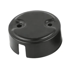
This page is about how an electric motor end cover is made by deep drawing — the route from flat coil to a finished end shield with bearing seat, bolt circle and ventilation, and why that route beats casting or machining at the right volumes. The companion page, deep drawn electric motor end cover, covers what to specify; this one covers what happens between coil and part.
The route, step by step
1. Blanking. Coil is blanked to a calculated diameter. Blank size is not guesswork — it sets how much metal flows into the wall, and it is logged per run together with lubrication, so a repeat order starts from numbers, not habits.
2. Drawing. A flat blank becomes the finished envelope in one controlled sequence. Shallow end covers draw in a single stage; deeper shells (bell-style covers, through-flow housings) draw in stages with interstage annealing, because steel that has been stretched hard will crack on the next pass unless it is softened first. The stage count is decided at quotation — it is visible in the tooling line, not discovered at first article.
3. Forming the flange and rim. The mounting flange and stiffening rim are formed in the same line. This is where the cover gains the flat annular face that bolts to the stator frame — and the face that springback will try to bow, which is why it is gauged on every run.
4. Trim and pierce. The mouth is trimmed to length and the ventilation slots, cable exits and fixing holes are pierced in following dies, after the geometry exists. Piercing before forming moves the holes; the sequence is the accuracy.
5. Secondary machining. The features a bearing actually cares about — bearing bore, pilot spigot, seal seats — are finish-turned on CNC centres to ±0.03 mm. Everything that runs or seals is machined; everything else stays as-drawn at ±0.1 mm. That split is the main cost lever on the part.
6. Cleaning and finishing. Degrease, then the drawing’s finish: zinc or nickel plating, e-coat, powder coat or passivation for stainless steel. Finishing detail is on the deep drawn covers guide.
Drawn vs cast vs machined end covers: the honest comparison
End covers can also be die-cast (aluminium) or machined from solid. Each route has a home turf:
| Route | Wins when | Gives up |
|---|---|---|
| Deep drawn (steel/stainless steel) | Volume steel programmes; thin walls; no seams needed; low unit cost after tooling | Dedicated die; complex external features need added ops |
| Die-cast (aluminium) | Complex 3-D features in one shot; when aluminium is required anyway | Porosity management; machining of critical seats still needed; tooling cost comparable |
| Machined from solid | Prototypes, very low volumes, exotic geometries | Unit cost scales with volume; buys precision in places that don’t need it |
The quotation states which route the volumes support — and for low-volume validation, stamping and forming alternatives exist under custom metal stamping.
Where the process is won or lost
- Blank-holder pressure and lubrication. The difference between a clean draw and a wrinkled flange is setup discipline. Settings are archived against the part number.
- Interstage annealing. Skipped annealing shows up as splits two stages later; the furnaces sit in line so the extra pass costs minutes, not days.
- The trim line. A mis-set trim shows as a height mismatch batch to batch; trim height is a named check on the sampling plan.
- Sequence for holes. All piercing after forming, through position fixtures — the reason hole patterns stay true to print without rework.
Quality control over the route
An ISO 9001 certified system governs the line: incoming material verified against mill certificates, first article measured on the CMM against the print, later batches following the agreed sampling plan. Cavity depth and seal-face finish are verified at first article; torque, leak and pressure tests are available where the assembly needs them, and the inspection report ships with each batch. Batch records are filed so a repeat order starts from approved data — the system detail is on quality control.
What this route costs
Two line items: tooling (the die, quoted as its own line — see tool & die design) and unit price (falls as volume amortises the die). First-article timing is measured from the tooling start date, so programme schedule is visible from day one. Delivery is FOB, CIF or DDP per Incoterms 2020, with call-off schedules supported.
Frequently asked questions
How many drawing stages does an end cover need?
Shallow covers: one. Bell-style or deep shells: two or more with interstage annealing. The stage count follows the depth-to-diameter ratio and the grade — stainless steel needs more stages than carbon steel at the same depth.
Why pierce holes after drawing instead of in the blank?
Because the metal moves during drawing. Holes in the blank distort and tear at the radius; holes pierced after forming, through fixtures, land on print. The sequence is the accuracy.
Can ventilation slots be formed rather than pierced?
Yes — lanced slots leave a formed tab that keeps airflow while blocking fingers and debris. Both pierced and lanced versions are produced; the choice depends on the print and the airflow requirement.
| Item | Deep drawing electric motor end cover |
|---|---|
| Brand | AUNOV |
| Designing | Driven by your drawing or a physical sample; unusual walls, threads or tolerances feasibility-checked first; revisions re-quoted once. |
| Tooling | Progressive and forming dies designed, built and maintained on site. |
| Samples | Issued for approval before the run; later batches gauged back to the signed sample. |
| Materials | Carbon steel (SPCC / DC01), 304 / 316 stainless steel, aluminium, brass — final grade fixed in the drawing review. |
| Surface finish | Plating, coating or polishing matched to duty; masking and laser marking available. |
| Processing | Multi-stage deep drawing with interstage annealing, trimmed and pierced in following dies; secondary machining on CNC centres. |
| Equipment | 5–250 T mechanical presses, 250–500 T hydraulic presses, in-line annealing furnaces, in-house toolmaking. |
| Tolerance | ±0.03 mm on turned secondary features, ±0.1 mm on as-drawn walls; capability checked on the first article. |
| Delivery terms | FOB, CIF or DDP per Incoterms 2020; T/T or L/C; USD or EUR; call-off schedules supported. |
Related Products


Request a Quote for This Part
Send a drawing or sketch — get material advice, tooling cost and a per-piece price within 24 hours (working days).