
Deep Drawn Airbag Gas Generator Housings

An airbag gas generator housing — also called an inflator housing, inflator cup or inflator can — is the drawn metal shell that holds the gas-generating charge and carries the ports the gas leaves through. It starts as a flat blank and ends as one continuous piece: a closed end, a short cylindrical wall, and a flange or rim that fixes the shell into the module. We form it on a press instead of rolling tube and welding on end caps, so the wall has no longitudinal seam. On a part where the closed end, the central boss and the ring of side ports all have to keep the same relationship to one another, that is the reason drawing is the normal route.
We run shells of this type on 5–500 ton presses to 150 mm deep, holding ±0.05 mm on a standard tool and ±0.02 mm where the wall is ironed. Those numbers come off our own tooling, not a catalogue. The guide to deep drawn tubes and cans walks through how a flat disc becomes a seamless wall, and the comparison of drawn, machined and welded housings shows what a weld seam costs at the sealing face.
Why the shell is drawn instead of welded
Build the same cup from tube and plate and you get three joints: tube to closed end, tube to top ring, and whatever boss or bracket sits on the closed end. Every joint is a place where heat moves the bore and where the wall gauge steps. A drawn shell has none of that. The metal runs unbroken from the closed end round the corner and up to the flange, so the wall you measure on the first article is the wall the part keeps.
Then there is the bore. A drawn bore is given by the punch, which is hardened steel and does not move between strokes. A welded tube inherits its outside diameter from the mill and its inside diameter from the wall tolerance, so two errors stack before the part is even assembled. When a flange, a boss or a port pattern has to be located off that bore, the difference shows up as scrap rather than as a drawing note.
The die is the expensive part; after that each shell is one stroke, and the ports and holes are separate stations on the same transfer or a follow-on press. The cost breakdown of deep drawn parts goes into where the saving actually sits. It is almost always in the repeat, not in the prototype.
What the photos show
The four photographs below are all of the same family of drawn cups. They are shop photographs, not renders: the surface scratches, the heat tint near the formed corner and the mixed orientations in the bulk container are all real. Captions stick to what is visible; no material grade, dimension or test result is inferred from a picture.
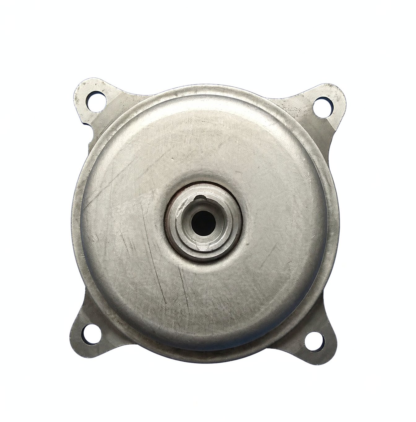
The first view is the one a designer usually starts from. There is a square flange with a hole in each corner, a large round dome pressed up out of the middle of the blank, and a smaller raised boss at the centre of that dome with a dark round opening. The corner holes and the centre opening are not made by the draw. They are pierced in later stations, which is what lets their position be held to the formed dome instead of to a flat sheet that will still move.
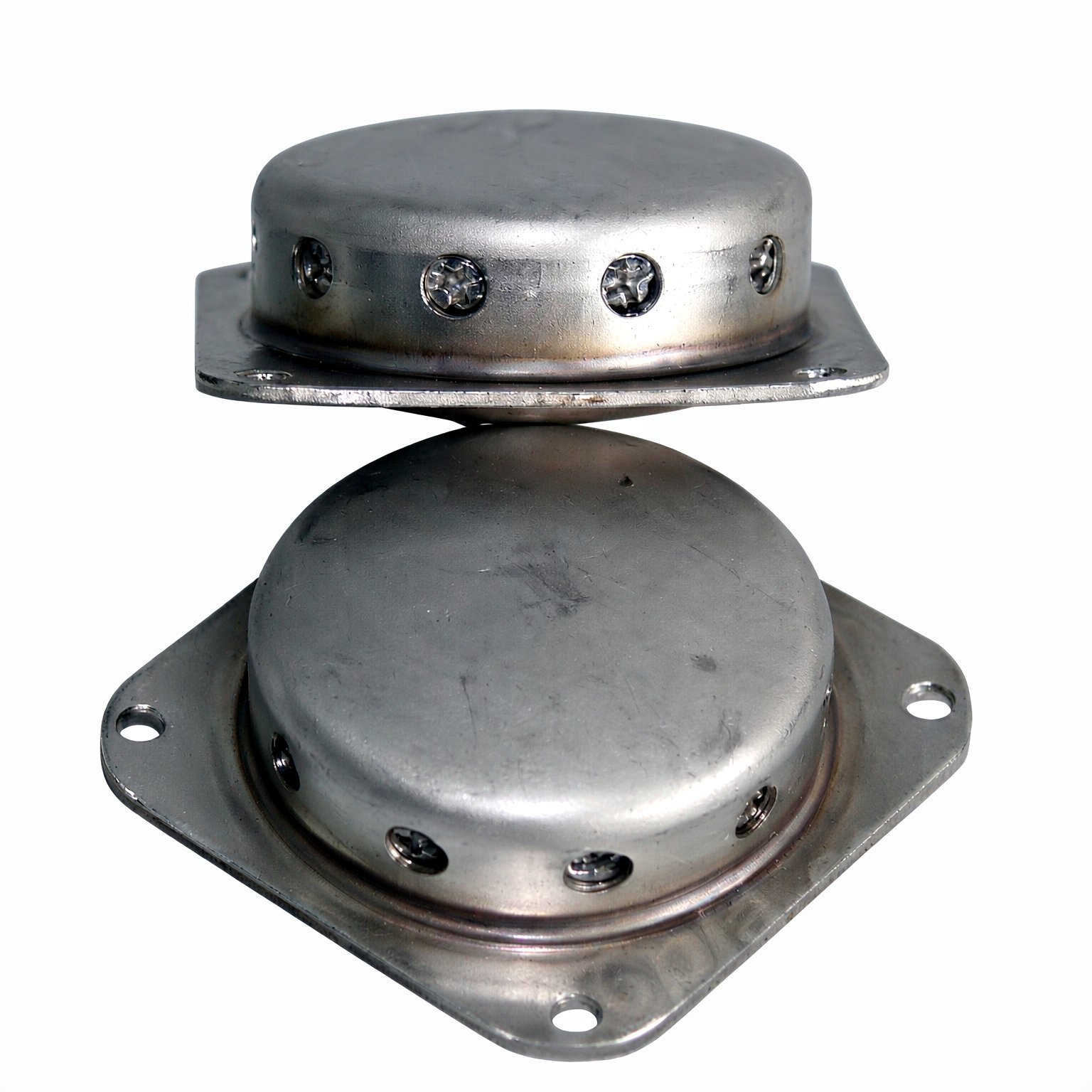
The second pair shows the wall detail. A band of round ports runs around the side of the short cylindrical shell, with a few pierced features that look different from the plain holes, and the flange again carries corner mounting holes. Some heat discoloration sits near the corner where the shell meets the flange. Ports like these are pierced after the cup is formed: the draw gives you the wall, then a side-piercing station gives you the holes, in one setup if the tooling is built for it. Where a port has to be burr-free on the inside, we deburr as its own operation and inspect it there, because a drawn wall is thin enough that a burr becomes a fit problem downstream.
From blank to trimmed flange
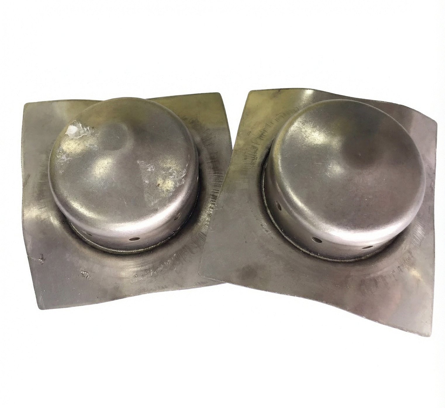
These two are earlier in the sequence. The dome has been pulled, but the square blank is still around it and the flange has not been trimmed to its final outline. You can see small round holes near the base of each dome, and the sheet around the formed corner has bowed slightly. That bow is normal: the blank is being pulled inward and the outer ring has not been cut away yet. Once the flange is trimmed, the part looks like the two finished housings above.
Whether the dome needs one pull or three is decided by the draw ratio, not by the press size. On our line the limiting ratio is 2.1–2.2 for DC04, 1.85–2.05 for 304 stainless steel and 1.80–1.95 for 5052 aluminium. Past that the shell splits at the punch radius, so a redraw or an anneal goes into the plan. The limiting draw ratio reference gives the planning ceiling by grade, and the maximum draw depth page explains what our 150 mm ceiling means in practice. Short, wide cups like these sit well below the ceiling; the awkward parts are the tall narrow ones.
Depth and wall control are separate decisions. A redraw changes the shape; ironing changes the wall. If a print calls out a controlled wall rather than just a starting gauge, that is an ironing pass, and it is also where the ±0.02 mm figure applies. We do not cut a thread into the drawn wall, and we do not publish one wall gauge for every housing: the wall thins near the punch radius and thickens toward the flange, so we agree the gauge on the drawing and measure the finished wall on the first article.
Volume, inspection and where our scope ends
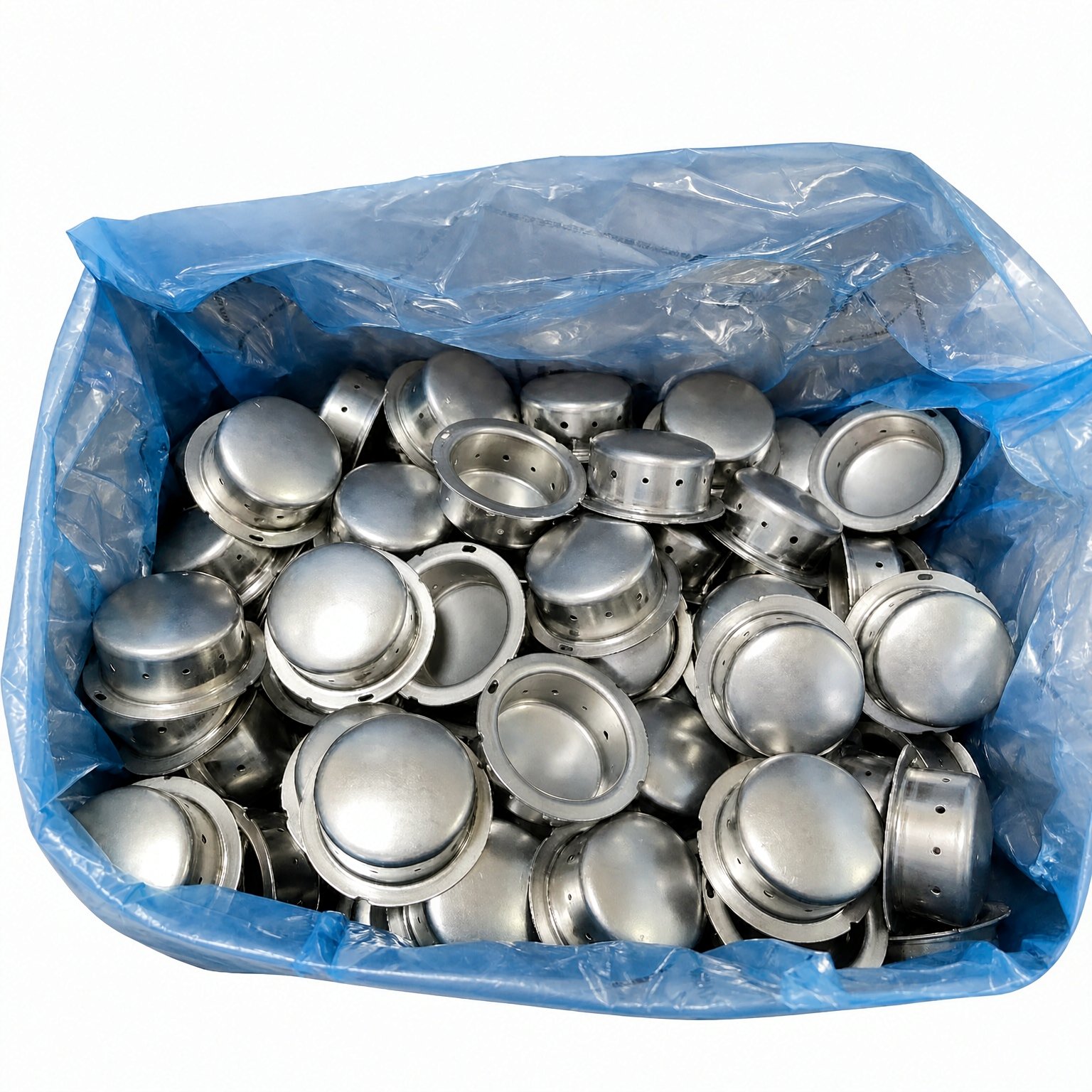
The last photograph is the part of the job that drawings never show. Cups come off the press in quantity, and the open ones make the geometry obvious: a hollow shell, a formed rim, small holes near that rim. At this point the useful questions are ordinary ones — is the bore the same as the first article, are the ports where the print says, is the rim flat enough to seat. We check the first article against the drawing, then hold the run on the dimensions the customer marks as sealing or locating features. The defect catalogue and the troubleshooting playbook cover what to do when the wall wrinkles, ears or splits instead.
Tooling is made in house, so the die and the first articles stay under our own control. Quotes come back within 24 hours, and the minimum run on new tooling is 1,000 pieces; repeat orders can be smaller because the die already exists. The MOQ, tooling and quote lead time page sets out the drawing fields we need to price a part.
One boundary is worth stating plainly. We make the drawn metal shell. Propellant loading, initiation, final assembly, and the qualification and validation of the finished inflator belong to the inflator manufacturer. We do not design the charge, specify the ignition train, or sign off a complete safety device; the print we work to is for the metal component.
What we do not claim
We do not publish leak-rate or burst-pressure figures for a housing we have not tested to an agreed method on our own line. What a shell will take depends on the wall we measure, the material, the closed-end shape and the flange design, so the test method is agreed with the customer before a number is quoted. We do not claim certification, homologation or approval for a complete airbag module, and we do not name vehicle programmes or tier customers. None of that follows from a forming capability.
We also do not say deep drawing removes every secondary operation. Ports, corner holes, the central boss and any thread are added after the shell is formed. And we do not say 6xxx aluminium draws like 5xxx; those grades are for shallow forming, with T6 applied afterwards. The comparison with impact extrusion covers the other route people ask about for closed-end cans.
Sources behind this guide
The forming behaviour above sits inside work maintained outside our shop.
- ASM Handbook, Volume 14B: Metalworking — Sheet Forming — deep drawing formability, wall thinning and redraw planning.
- ASTM A240/A240M — the specification stainless steel sheet is commonly supplied against.
- ISO 20482 — Erichsen cupping test, a formability measure complementary to draw ratio.
- Wikipedia: Deep drawing — background on the draw, redraw and ironing sequence.
How to send us a housing print
Send the cup diameter and depth, the closed-end shape, the flange outline and bolt-hole pattern, the port size and pattern, the wall gauge, the material grade, and the dimensions marked as sealing or locating features. Tell us which faces have to be burr-free and how the part is seated in the next assembly. We do not need any detail of the charge or the ignition train. We will say whether the cup draws in one pull or needs a redraw, where the ports and boss sit as secondary work, and what the first-article check will cover. Tooling is in house, quotes come back within 24 hours, and the minimum run on new tooling is 1,000 pieces.
Frequently asked questions
What does a deep drawn airbag inflator housing do?
It is the seamless metal cup that contains the gas-generating charge and carries the ports the gas exits through. One flat blank is formed into a closed end, a short wall and a flange, so there is no longitudinal weld seam in the wall. The flange fixes the shell into the module; the boss, the corner holes and the ring of side ports are added as secondary operations after the draw.
Why draw an inflator cup instead of welding it from tube and plate?
A welded cup stacks three joints and two sets of tolerance before the part is assembled, and each weld moves the bore with heat. A drawn cup is one continuous piece of metal, so the wall stays consistent from the closed end to the flange and the inside diameter repeats to ±0.05 mm because it is set by the punch. At volume it is also one press stroke per shell once the die is built.
Can the vent ports and flange holes be formed in the same press stroke as the draw?
No. The draw forms the wall and the closed end; ports, corner holes and the central boss are pierced in later stations, often on the same transfer tool but never by the forming stroke itself. Piercing later is what lets hole position be referenced to the formed dome. Where an inside face has to be burr-free, deburring and inspection are their own operations.
What tolerances can a deep drawn inflator housing hold?
We hold ±0.05 mm on a standard tool and ±0.02 mm where the wall is ironed, on 5–500 ton presses with depth to 150 mm. The tightest repeating dimension is the bore, because the punch defines it. Ports, holes and the boss are toleranced as secondary features on the drawing, and the wall gauge is agreed on the print rather than quoted as a single number for every housing.
Which materials can be drawn for an airbag gas generator housing?
Low-carbon steel such as DC04, 304 stainless steel and 5052 aluminium are the grades we plan draws around, with limiting ratios of 2.1–2.2, 1.85–2.05 and 1.80–1.95 respectively. The choice follows the print: strength, corrosion, weight and what the shell is seated against. 6xxx aluminium is a shallow-forming grade with T6 applied afterwards, not a substitute for 5xxx in a deep draw. The photographs here do not establish a grade; that comes from the drawing.
What is the minimum order and quote lead time for a drawn inflator housing?
The minimum run on new tooling is 1,000 pieces, and repeat orders can be smaller because the die already exists. Tooling is made in house. Quotes come back within 24 hours once we have the diameter, depth, wall gauge, material, flange pattern and port pattern. The gate is the die and the first-article check, not the press time.
Do you supply or validate the finished airbag inflator?
No. We make the drawn metal shell to a customer print. Propellant loading, initiation, final assembly and the qualification of the complete inflator are the inflator manufacturer’s scope. For that reason we do not publish leak-rate or burst-pressure figures for a housing we have not tested to an agreed method on our own line, and we do not claim certification or approval of a complete safety device.
Key point: An airbag gas generator housing is a seamless drawn cup whose closed end, mounting flange, central boss and vent ports all start from one flat blank.
Last reviewed: 2026-11-13 · Reviewed by Sam Zhang, Process Engineer