
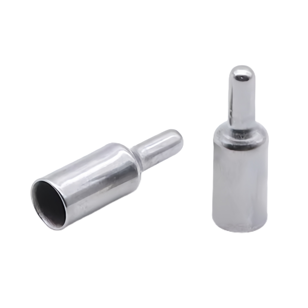
The Steel Deep Drawn Cup with Stem Probe Shells is a two-feature part: a closed cup that houses the sensing element and a slender stem that carries the shell into the process medium. The engineering interest is in the relationship between those two features – the stem must run true to the cup, the wall must survive the transition between them, and the whole shell must accept a potted sensor without rework. This page covers the forming plan, the transition zone and the acceptance checks specific to probe shells.
Cup and stem in one shell: what the geometry demands of drawing
A probe shell is not a deep cup with a decoration; it is a shell where two functional zones coexist. The cup interior is the sensor’s cavity – its depth and bore set the size of everything that must fit inside – and the stem is the mounting interface, the surface that seats into a thermowell boss or a process wall. Forming both from one blank means the metal has to flow much harder into the stem region than into the cup, and the draw stages are planned so the stem does not thin while the cup is still being formed.
- The route is staged drawing: the cup is established first over successive die rings, then the stem is drawn out of the cup’s closed base in one or more finishing passes – the reverse sequence would leave the stem unsupported through every cup stage and it would not survive the handling between them.
- Depth beyond roughly twice the diameter anywhere on this route means in-line annealing between stages; the stage plan is itemised in the quotation because it is the main driver of both tooling cost and lead time.
- The stem’s wall gauge is set by the last pass’s plug and die ring pairing, and we draw the stem deliberately over-gauge where it will be machined to the fit – typically leaving 0.15-0.25 mm per side on diameters that must hold ±0.03 mm.
Coaxiality between stem and cup: the number the assembly lives on
When a probe shell screws or slides into a thermowell, what matters is that the stem’s axis and the cup’s axis are the same line. A stem that runs eccentric to the cup by even a few hundredths of a millimetre means the shell seats crooked, the sensor element tilts inside, and in a tight well the stem can bind against the bore. Coaxiality is therefore the named measurement for this part family – ahead of any single diameter on the print.
- Because both features come from the same blank and the same die centre, the drawn part starts with a natural coaxiality that machining then refines rather than creates; this is the deep-drawing advantage over a turned-and-brazed construction, where two axes are joined and never truly merge.
- We machine the stem’s fit diameter against the cup’s datum in a single setup, so the reported stem-to-cup runout is a result of one clamped operation, held to the ±0.03 mm class on machined features.
- Where the print is silent on coaxiality, the drawing review raises it – a probe print without a runout call is a print waiting for an assembly problem, and it is cheaper to add the call-out than to discover the tolerance empirically in a thermowell.
The transition zone: where the wall must neither fold nor crack
Between cup base and stem there is a transition – a shoulder, radius or taper – and it is the highest-strain real estate on the part. The metal that becomes the stem wall is drawn out of the cup’s base, and at the transition it changes direction while thinning. Two failure families live here: circumferential cracking when the stage reduction is too aggressive for the anneal state, and circumferential folding when the stage tries to push too much metal through too small an opening. Both are prevented upstream, in the stage plan, not corrected downstream.
- Stage reductions at the transition are kept within ratios the material’s anneal condition supports, with in-line annealing resetting the shell between passes so the metal draws instead of splitting.
- The transition radius is a drawing-review item: a radius opened by even half a millimetre can remove an entire draw stage, and we quote that trade explicitly because it is real money on tooling.
- Wall thickness at the transition is a named first-article measurement – mapped, not spot-checked, because the thin section predicts how the shell behaves when it is clamped into service and the stem takes side load.
Inside the cup: what the potting and the element need from the bore
The cup interior is a functional space even though no gauge ever touches it in our plant. A potted sensor fills this cavity with epoxy or thermal compound, and two properties of the bore decide the assembly’s success: its volume consistency and its surface condition. A bore that varies in depth or diameter across a batch changes the thermal mass around the element, which shows up as calibration drift between probes that were built identically.
- Cup depth and bore diameter are measured at first article with the full report archived, so the customer’s potting line receives a documented cavity rather than a statistical hope.
- The drawn bore carries the texture of the plug that formed it; where the potting compound must wet the wall, we control the as-drawn texture and, where the print demands more, the bore is machined or finished to the stated Ra rather than left as a process by-product.
- Cleanliness is a specification for probe work: shells leave the line degreased and free of drawing lubricant residue, because a film the eye cannot see can delaminate a potting bond the calibration depends on.
Steel, protection and the wet-service question
Probe shells serve in process lines, coolant loops and outdoor enclosures, and the material-plus-finish decision must be made against the medium, not the catalogue. Carbon steel SPCC / DC01 with zinc plating handles dry and indoor duty at the lowest cost; where the stem is permanently wet, the review moves to 304 or 316 stainless steel – drawn here with the staged anneals stainless steel demands – or to nickel or chrome plating over the steel.
- On plated steel shells, the deposit has the same duty as on any drawn part: thickness and adhesion verified on the first article, with the finish written into the drawing revision so the decision is made once.
- Where the stem seals against an elastomer, the stem’s surface texture is a sealing parameter, and we finish it to the drawing’s stated Ra instead of letting the drawing route’s default texture carry the seal.
- The wet-service question is asked before the die is cut because it changes material, stages and finish at once – the most expensive place to discover it is after the first batch is in service.
How we verify a probe shell before it reaches the potting line
The acceptance sequence is written per part number and runs unchanged from first article through production.
- CMM first article in the climate-controlled room: cup depth and bore, stem diameter and length, and stem-to-cup coaxiality as the governing runout measurement, all against your print.
- Wall mapping: thickness at the transition zone and at the documented thinnest section of both features, recorded so the customer knows the structural margin, not just the envelope.
- Fit verification: the stem’s machined land gauged to its ±0.03 mm class, with surface texture verified where the print calls a seal or sliding Ra.
- Interior condition: cup bore texture and cleanliness per the probe cleanliness specification.
- Material and finish evidence: mill certificate per heat, plating or passivation records tied to the drawing revision, and the signed first article that every production batch is gauged back to under ISO 9001.
Deep Drawn Tubes & Sleeves is the parent range for parts like this one; the overview page gathers the tooling logic, finishing options and tolerance notes that apply across the family.
Specifications
| Item | Steel Deep Drawn Cup with Stem Probe Shells |
|---|---|
| Brand | AUNOV |
| Designing | Send drawings, or send a shell sample to be measured, a manufacturability review comes back with the quotation. |
| Tooling | Dies designed and built in our own toolroom, each die held against your part number. |
| Samples | First articles go out with dimensional data plus material certs. |
| Materials | Carbon steel (SPCC / DC01) is the primary stock for this part, alongside 304 / 316 stainless steel, aluminium, brass and copper, and the grade is fixed at the drawing review. |
| Surface finish | Plating, e-coat, powder coating, anodising or passivation as the drawing calls out, fixed at the drawing review. |
| Processing | Deep drawing in stages, in-line annealing where needed, then pierced and CNC-machined in house. |
| Equipment | 5-250 T mechanical presses plus 250-500 T hydraulic presses, in-house CNC cells and a temperature-controlled inspection room. |
| Tolerance | Drawn tolerances held to +/-0.1 mm, with machined features to +/-0.03 mm. |
| Delivery terms | Prices FOB, with DDP for EU and US on request, T/T and L/C; D/P on repeat accounts, scheduled call-offs welcome. |
Related Products
Request a Quote for This Part
Send a drawing or sketch — get material advice, tooling cost and a per-piece price within 24 hours (working days).