
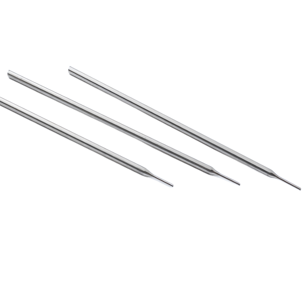
The Stainless Steel Precision Ground Needle Pin is a small-diameter shaft whose whole value is made on the grinder: diameter to a few thousandths of a millimeter, roundness measured in tenths, and tips that mate on first contact. Below: centerless grinding at pin scale, the tip geometries that prevent jamming, and the sampling logic that makes a thousand-piece bag statistically trustworthy.
Centerless grinding to five thousandths on a 1.5 mm pin
A ground needle pin is produced on a centerless grinder, and centerless is a process with personality. The work is supported by a blade and driven by a regulating wheel – no centers, no chuck, no centers to be out-of-true – which is precisely why it is the right process for 1 to 3 mm pins that would deflect in a lathe and why its failure modes are all in the setup. Through-feed grinding runs the part axially between the wheels for parts that are uniform along their length; infeed (plunge) grinding handles profiles, tapers and steps by feeding the wheel radially into a stationary part. Needle pins use both: through-feed for straight pins, plunge for stepped or tapered shanks.
At 1.5 mm diameter the challenges concentrate. Wheel pressure can bow the pin during plunge, so we run small plunge depths in roughing passes and a spark-out dwell on the finishing pass – dwell time, not depth, is what buys the last thousandth. The blade angle and work height above center control the rounding action: set correctly, an out-of-round part gets progressively rounded pass by pass; set wrong, the process reproduces the lobing it was supposed to remove, and the part measures a good diameter while being a bad shape. We qualify the rounding behavior on every new pin setup with a roundness check on the first five parts off the machine, because that check tells us more about the setup than an hour of micrometer work.
Size control is a temperature and wheel-dress discipline. The grinding zone heats the pin; stainless steel conducts that heat away slowly for its size, and a pin measured warm measures small when it cools. Our grinders sit in the same climate-controlled building as our CMM room, parts are measured at temperature on a defined dwell, and wheel dressing happens on a fixed interval rather than on operator judgment, so the wheel is never quietly growing dull and burning. The capability we quote as standard is +/-0.005 mm on ground diameter, with tighter bands available on request through additional passes and 100 percent gauging – the quotation states which is being priced.
Tip geometry: the shape that decides whether it mates or jams
On a needle pin the tip is not decorative – it is the interface. A flat-cut tip meeting a slight misalignment in the mating bore presents a sharp edge that digs, shaves a burr into the bore, and jams. A full radius presents a tangent contact that centers itself. Between the two lies a family of practical geometries, each matched to a duty:
- Full radius (ball end) – for pins that must find and center in a seat under tolerance stack; the default for valve-needle and probe duties. We generate it by plunge grinding with a dressed radius in the wheel, and verify it optically against a projected overlay.
- Chamfered tip at 30 to 45 degrees – for pins that enter a plain bore; the lead-in converts insertion misalignment into sliding rather than digging.
- Tapered point – for metering and positioning duties where the tip is the working element; here the taper angle and the concentricity of the point to the shank are both named dimensions on the inspection plan.
- Flat-cut tip with broken edges – acceptable for pilot pins in non-critical locations; the cheapest to make and the easiest to recognize as the wrong choice on a demanding assembly.
The lesson we bring from field failures: tip concentricity is the silent killer. A perfect radius ground off-axis to the shank runs in a seat exactly as badly as a jamming flat. Our tip grinds are set up so the radius is generated in the same setup as the final shank pass wherever the geometry allows, and tip runout is a named first-article check at 10x magnification plus CMM where the part size permits.
Roundness, straightness and the measurement nobody budgets for
Pin quality has three geometric dimensions and each has its own instrument. Diameter is measured with a laser micrometer or a matched-ball micrometer – a pin measured between flat anvils at three rotations gives three different answers on an out-of-round part, and the micrometer averages exactly the error you were trying to catch. Roundness is measured on selected parts on a precision spindle or by the three-point V-block method, and it is the one parameter that cannot be fully verified with two-point tools, because even-lobe roundness errors are invisible to two flats. Straightness is checked by rolling each pin under a dial indicator supported on a surface plate or on a straightness gauge – a 30 mm pin with 0.02 mm of bow fits a nominal bore and binds halfway in.
We fold these into the process rather than bolting them on at the end: the roundness qualification on the first parts of each setup, straightness sampling per lot on a defined plan, and 100 percent diameter gauging for orders supplied to tight bands. Sorting by feeler gauge and experience is not a quality plan at pin scale; the parts are too small to inspect manually with any consistency, so the gauging must be instrumental and its results numeric.
One process note on straightness specifically: centerless grinding does not correct incoming bend, it corrects diameter. If the blank is bent, the ground pin is a straightened-looking version of the same bend within the limits of what the blade support forced during grinding. So the blank preparation upstream – cut to length without kinking, handled in trays rather than bins – is part of the pin process, not overhead. We handle blanks in rigid trays throughout, and this discipline costs nothing and is audited in our routing.
Consistency by the thousand: batch logic for small pins
Needle pins are consumed in volume, and the customer’s real specification is that bag number 400 behaves like bag number 4. Batch consistency at this scale is a statistical commitment, not a promise, and it is structured in the plan. The first article establishes the center of the process window – wheel dressing interval, feed, dwell, and measured output on those settings. Production runs against that documented window with a defined sampling frequency: size measured per interval on sampled parts, results recorded, and the process center tracked so drift is corrected before parts reach the tolerance limit rather than after. This is textbook statistical process control, and the reason we run it on pin work is that pins are the product category where a drifting process produces the most quietly-wrong parts per hour of anything we make.
Two cost levers worth knowing at quotation time. First, packaging density: loose-bagged pins scratch each other in transit on their ground surfaces, so our standard pack for ground pins is layered trays or interleave, and “bulk bag” is offered with a surface note rather than as a silent downgrade. Second, mixed-length kits: where an assembly uses several pin sizes, we can supply a single kit with sizes separated and labeled, which moves sorting effort from your line to ours where it is cheaper; the per-piece premium is small and the line-side savings are real.
The final element of batch trust is the record. Every pin lot carries its process window record, sampling results and material certificate under our ISO 9001 system, keyed to the part number. A reorder is set up from that record – same dressing interval, same feeds – which is why reorders of ground pins are consistent in a way that “same drawing, new run” is not on an undocumented process.
How we verify ground pins before they ship
The verification plan for needle pins, applied to every lot against the signed first article:
- Diameter – laser or micrometer measurement per the sampling plan, 100 percent for tight-band orders, with results recorded numerically per sample rather than as pass/fail.
- Roundness – spindle or V-block three-point method on the first parts of each setup and on the lot sample plan, with even-lobe errors explicitly checked by the method choice.
- Straightness – surface-plate roll or straightness gauge per sample plan, reported as bow over length.
- Tip geometry – projected overlay or optical comparison against the specified radius, chamfer angle or taper, checked on the first article and again per sample plan; tip runout to shank checked on profiled parts.
- Surface condition – visual at 10x for grind burn discoloration and handling scratches, with burn treated as a reject-and-investigate event rather than a cosmetic call.
- Pack and record – layered packing verified, lot records with process window and sampling data archived under our ISO 9001 system, and reorders set up from the archived window so lot 400 matches lot 4.
Send the mating bore diameter and tolerance with the pin drawing, and the first article will arrive with the fit demonstrated on gauges rather than asserted on paper.
Deep Drawn Tubes & Sleeves is the parent range for parts like this one; the overview page gathers the tooling logic, finishing options and tolerance notes that apply across the family.
Specifications
| Item | Stainless Steel Precision Ground Needle Pins |
|---|---|
| Brand | AUNOV |
| Designing | Share your print, or send a part to be measured, a manufacturability review comes back with the quotation. |
| Tooling | Dies designed and built in our own toolroom, each die held against your part number. |
| Samples | First-off samples of the pin are sent with a dimensional report and material certificate. |
| Materials | 304 / 316 stainless steel leads the stock list for this part, alongside carbon steel (SPCC / DC01), aluminium, brass and copper, with grade selection confirmed at drawing review. |
| Surface finish | Zinc, nickel or chrome plating, e-coat, powder coat, anodising or passivation, per the drawing. |
| Processing | Staged deep drawing with in-line annealing where needed, with piercing and finish machining under the same roof. |
| Equipment | Mechanical presses 5-250 T, hydraulic presses 250-500 T, CNC cells plus a temperature-controlled CMM room. |
| Tolerance | Drawn tolerances held to +/-0.1 mm, with machined features to +/-0.03 mm. |
| Delivery terms | Prices FOB, with DDP for EU and US on request, T/T or L/C, D/P on repeat business, call-off schedules and blanket orders supported. |
Related Products

Request a Quote for This Part
Send a drawing or sketch — get material advice, tooling cost and a per-piece price within 24 hours (working days).