
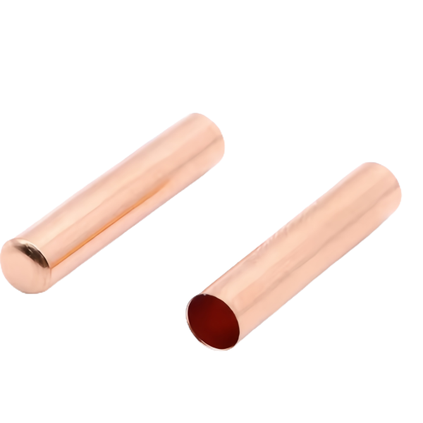
The Copper Deep Drawn Tube – closed end or open – is a pressure-holding shell made from one of the most forgiving and most work-hardening metals we run. On this page we cover copper’s annealing windows, the bottom-thickness arithmetic on closed-end shells, the open-end finishing options, and the leak test that turns a formed cup into a qualified part.
Drawing copper: the work-hardening windows between anneals
Copper draws beautifully and punishes greed. Annealed C11000 or C26000 flows in a die ring like few other metals, which tempts aggressive single-pass reductions – and copper work-hardens so steeply that the second aggressive pass tears, even though the first looked effortless. The whole discipline of copper deep drawing is staged reduction with anneals in the right places, and the schedule is material physics, not shop folklore: around 35 percent reduction per stage is a comfortable ceiling for annealed copper, but consecutive stages without intermediate annealing must drop sharply in severity, because each stage leaves the shell harder and more brittle than the last.
Our routing for closed-end copper tubes alternates draw stages with in-line annealing – the same anneal-in-the-flow discipline we run on stainless steel programs, tuned to copper’s faster recovery. The tell-tale we watch is flange wrinkling at the open end: wrinkles mean the blankholder pressure and lubrication have drifted from window, and on copper that drift announces itself early enough to correct before a stage produces torn shells. Lubrication on copper deserves its own sentence because it decides both surface and tool life: we use film lubricants compatible with the annealing sequence – a residue that carbonizes in the annealer is worse than a slightly less slippery but clean-burning compound.
Grain size is the quiet variable underneath everything. Over-annealed copper grows coarse grains that pebbled visibly on the drawn wall and fails in service at lower fatigue cycles; under-annealed copper cracks in the next draw. We set anneal temperature and time against the cup’s stage history, and we verify with a hardness check per anneal lot and a grain-size metallographic check at first article – the latter is the only measurement that speaks directly to what annealing actually did.
Closed end: bottom thickness and where shells actually fail
A closed-end deep drawn tube is a pressure vessel, and its weak point is arithmetic, not luck: the bottom corner radius, where the shell has been through the most severe deformation and the wall carries biaxial stress in service. During drawing, material at the corner thins – a well-tuned ironing pass holds thinning to 5 to 10 percent, a poorly tuned one takes 20 percent or more, and a 15 percent thinner corner on a 0.8 mm wall is the difference between a shell rated comfortably and one that fatigue-cracks at the radius after N thousand cycles.
We treat corner thickness as a named dimension with a named process:
- Ironing to size – the final stages size the wall deliberately, with the punch and die ring gap setting thickness; this simultaneously improves the wall uniformity that free drawing leaves scattered.
- Corner radius on the tooling – generous punch radii in early stages and the final corner formed at the end, so the corner is made once under controlled conditions rather than worked repeatedly.
- Sectioned first article – the first article is cut through the corner and the wall profile is measured point by point; the measured profile, not the nominal, is what the inspection plan is written against.
- Bottom thickness – measured at center and at the corner transition on the sectioned article, because bottom center and corner behave differently and a single measurement at one spot hides the other.
The failure mode all of this prevents has a signature: slow leak at the corner radius, appearing after pressure cycling, invisible to a proof test but certain to appear in the field. This is why our leak and fatigue discussion with customers always ends up back at corner thinning – it is the honest place to spend engineering attention on a closed-end shell.
Open end options: trim, chamfer, bead and the seal it meets
An open-end copper tube is rarely finished as-drawn – the end is where it meets something. The menu of end conditions is worth choosing deliberately, because each option has a function it serves and a cost it earns. Trim to length is the base operation, run against a positive length stop, the cut geometry chosen to avoid smearing copper into the bore – copper is soft, and a rough cut folds a burr inward that is trivial to make and tedious to remove. Chamfering both edges, outer for handling and inner for insertion, is cheap insurance and our default recommendation when the end enters a fitting.
Where the tube seals mechanically, the options expand:
- Plain round end for brazing – end squareness controlled, surface clean and oxide-free for the joint; the routing includes a solvent wash positioned after all forming so the braze face is as-shipped condition.
- Beaded end for a rubber or O-ring seal – a rolled bead formed in a die against internal support; bead height and width are named dimensions, verified with a groove micrometer on the sample plan, because a bead 0.1 mm low does not seal and 0.1 mm high does not insert.
- Expanded or reduced end for tube-to-tube fit – a sizing pass that sets the end to grip its mate; fit is verified by gauge or by trial-mating to a master pin, which is the acceptance event that matches reality.
Copper’s softness makes all of these end operations fast – and makes their fixturing delicate. Every forming step at the open end runs with internal mandrel support sized to the bore, because unsupported copper deforms under its own clamping force and the error is invisible until the mate does not fit.
Leak-tightness: what test pressure proves and what it cannot
A closed-end copper shell has one non-negotiable acceptance event: the leak test. The choice of method is a real engineering decision because each method detects a different failure class. A straightforward pressure-decay test at a multiple of service pressure catches gross leaks and verifies the shell holds proof load. A more sensitive pressure-decay setup with temperature compensation catches smaller leaks. Bubble testing underwater is simple and visual but operator-dependent at the small-leak end. For the finest cracks – and copper corner fatigue cracks are fine – nothing short of a helium or halogen tracer method is definitive, and that is a test we would specify only where the duty genuinely demands it, because it is an expensive answer to a question most products do not need asked.
What we insist on regardless of method is testing after all processing, not before – a shell that leaks after trimming or bead-rolling was telling you something about residual stress, and testing at the wrong point in the routing only catches defects the later operations did not create. Our standard for closed-end copper tubes is pressure-decay leak testing of every part at a specified proof pressure with a defined decay limit, parameters archived with the lot; the acceptance criterion is stated as pressure held over time, a number your quality system can audit, not “no visible bubbles”.
One note on cycling duty: proof testing proves static integrity, nothing else. Where the application pressure-cycles – a sensor bulb, a pulsing hydraulic line – the fatigue question has to be answered by design (corner thinning budget, as above) and by life verification on a sampled destructive basis if the duty is critical. We flag this conversation at quotation time, because it is the one requirement that cannot be inspected into a finished shell.
How we verify wall, bottom and leak integrity on copper tube lots
Each copper tube lot – closed or open end – answers to the signed first article with these checks:
- Wall profile – sectioned first article with point-by-point wall measurement from bottom center through the corner; production wall verified by ultrasonic or sectioned sampling on the lot plan.
- OD, ID and concentricity – measured at defined stations on the sample plan, wall spread reported as the concentricity evidence, in our climate-controlled measuring room.
- Grain and hardness – hardness per anneal lot in the routing; grain-size metallography at first article and on material-lot changes.
- End condition – length against hard stop, squareness and chamfer at 10x, bead or sizing dimensions gauged or trial-mated to a master on the sample plan.
- Leak test – every closed-end part pressure-decay tested at specified proof pressure with a defined hold and decay limit, results archived per lot.
- Cleanliness and record – solvent wash in the routing after final forming, coil and anneal certificates tied to the lot, all under our ISO 9001 system so reorders are drawn on the proven schedule.
Send the service pressure, the cycling expectation and the sealing method, and the first article ships with the corner profile, leak parameters and end condition demonstrated on parts you can hold.
This part belongs to our Deep Drawn Tubes & Sleeves range. The deep drawn tubes & sleeves pages collect the process notes, common materials and inspection points behind every product in the family.
Specifications
| Item | Copper Deep Drawn Tubes Closed and Open End |
|---|---|
| Brand | AUNOV |
| Designing | Send the drawing, or a sample we can measure, a manufacturability review comes back with the quotation. |
| Tooling | Dies designed and built in our own toolroom, each die held against your part number. |
| Samples | First-off samples are sent with a dimensional report plus material certs. |
| Materials | Copper is the primary stock for this part, alongside carbon steel (SPCC / DC01), 304 / 316 stainless steel, aluminium and brass, with the final grade confirmed at the drawing review. |
| Surface finish | Surface treatment per the drawing: plating, e-coat, powder coating, anodising, passivation, per your print. |
| Processing | Staged deep drawing with in-line annealing where needed, pierced and finish-machined on the same floor. |
| Equipment | Presses run 5-250 T mechanical and 250-500 T hydraulic, with CNC turning centres and a climate-controlled CMM room for inspection. |
| Tolerance | As-drawn tolerance +/-0.1 mm, +/-0.03 mm after machining. |
| Delivery terms | Prices FOB, with DDP for EU and US on request, T/T and L/C; D/P on repeat accounts, call-off schedules and blanket orders supported. |
Related Products


Request a Quote for This Part
Send a drawing or sketch — get material advice, tooling cost and a per-piece price within 24 hours (working days).