

An end-closed sensor tube looks like a test tube with a wire coming out of it. That appearance hides a manufacturing problem that is harder than it looks: you have to put a heat-generating resistive element inside a sealed metal tube, close the tube around it, and do it without creating either a leak path or a stress concentration that will crack under the next thermal cycle.
The order of operations is the whole design. Everything about this part follows from what has to be inside before the metal closes.
The metal has to close over something that is already in there
There are two routes, and the choice determines almost every downstream detail.
- Draw a cup, then insert. A shallow cup is drawn, the sensor is placed inside, and the cup is drawn again to close and to reach the final length. This is the natural route for a short closed tube. It gives a formed closed end with a genuine transition radius, and the sensor is positioned by the closing operation rather than by a separate step.
- Draw a tube, then form the end. The tube is drawn to length, the sensor is inserted into the open end, and the end is closed by a forming operation — a necked-in and flattened, or a stamped cap, or a welded closure.
The first route produces a better part and is limited in length. Once the drawn depth exceeds roughly two to three times the diameter, the tool forces required to draw the wall down to that length become large and the draw becomes sensitive to every variation in the blank. Beyond that point, route two is the only practical answer even though route two makes a worse part.
Why the drawn cup route gives a better closed end
The closed end on this style of part is where the part either works for ten years or fails in the first year, and the difference is entirely the transition.
In a drawn cup, the transition from the cylindrical wall to the flat bottom is a continuous flow of material with a natural radius, formed in one operation while the material is in its most ductile state. The wall is thinnest at that transition — that is inherent to drawing, since material travels furthest to reach the corner — but the thinning is gradual and the geometry is smooth.
In a closed-end tube made by necking, the wall is deformed over a much tighter radius in a much less ductile state, and the corner is where the deformation is most concentrated. This produces three failure modes that show up in service rather than at the bench:
- Longitudinal cracking. The material has exhausted its elongation at the corner and cracks along the axis of the tube. The crack may not reach the surface, so it passes a visual inspection.
- Micro-cracking that becomes a leak. A through-crack opens only after the first thermal cycle, at a joint the customer believes is sealed.
- Work-hardening that removes all ductility. The closed end is the hardest part of the tube, and if the assembly requires any subsequent forming or the part is handled roughly in transit, the failure initiates there.
None of this appears on a dimensional report. The geometry is within tolerance in every case. Detecting it requires either a sectioned first article with a metallurgical look, or a pressure test, and preferably both.
Wall thinning at the corner is unavoidable, so it has to be specified
Because the corner thins, the drawing needs two wall figures rather than one:
- The body wall, measured where the drawing can reference it easily.
- A minimum wall at the closed-end transition, which is always lower than the body wall.
The second figure is the one that governs whether the part survives. On a tube that will see pressure, the transition wall usually becomes the design wall for the entire part, which is a good way to see why the body wall often has more material in it than the body requires.
The measurement has to be made on a sectioned sample, because no non-destructive method reliably resolves a corner radius at production rate. That is acceptable as a first-article check and unacceptable as a production check, so production control has to come from process capability rather than from measurement — the drawing should say which of the two applies to which characteristic.
The thermal path inside a closed tube
The sensor element has to be close to the end that touches the process. Inside a closed tube, there are three arrangements and the difference between them is a factor of several in response time.
- Element at the closed end, in contact with the wall. The shortest heat path, the fastest response, and the most accurate. The requirement is that the contact is thermal, not merely positional.
- Element held off the end by a short standoff. Acceptable when the assembly requires clearance for the element’s leads, at the cost of a lag proportional to the standoff distance.
- Element floating in the middle of the tube. The worst case, because heat has to travel axially and then radially, and the bore air or filler between element and wall is a poor conductor. Used only when the tip is deliberately insulated from the process.
In all three cases the space that is not occupied by the element is filled with something, and what it is filled with matters as much as the element’s position. Air is an insulator. A thermal filler after cure is a conductor. A structural epoxy that is perfectly adequate as an adhesive can be a poor thermal conductor, and the resulting error is invisible until the part is compared against a reference.
So the specification needs to name the filler, its thermal conductivity in the cured state, and its temperature rating. This is one of the most commonly unspecified items on parts of this type, and one of the most consequential.
How the wire leaves, and why the method constrains the process
The wire entry through the closed end or the side wall is the leak path that has to be designed rather than discovered.
Glass-to-metal hermetic seal is the right answer wherever the part must hold pressure, hold refrigerant, or enter a hermetically sealed assembly. The seal is formed by drawing the metal to close around the glass at temperature, which gives a metallurgical bond and a leak rate orders of magnitude below any elastomer. Its requirements are strict: the metal has to be in the correct grain condition for the operation, the glass has to be matched to the thermal expansion of the metal, and the assembly must be fired at a temperature the sensor can survive. On a thin-wall drawn part, that means the seal is often formed before the tube is drawn to its final size, so the drawing operation cannot distort it.
Epoxy or cement fill is adequate where the tube does not have to hold pressure. Its limitation is not strength but longevity: the fill shrinks over thermal cycling, and a shrinking fill eventually opens a path that a cured mass was not supposed to have. On a part that sees hundreds of thousands of cycles, this is a real failure mode.
Mechanical feedthrough — a crimped or threaded gland — is the option for high-current or replaceable sensors, and it is the least reliable for sealing while being the most robust mechanically. Where it is used, the gland should be a separate specified item with its own torque and leak requirement.
The number of conductors is also a design decision with a cost. Each additional conductor is another hole or a larger gland, and on a hermetic seal the conductor count affects the seal’s geometry. Two-wire is the cleanest thermally and mechanically.
Drawing practice on a closed-end tube
Some specifics that matter and are not on the print:
- Blank preparation. The blank edge condition determines how much the material can stretch at the corner. A rough or damaged blank edge will crack at exactly the transition we are trying to protect.
- Lubrication. Drawing lubricant affects not only the die but the surface finish, and the finish of the inside of the closed end is the surface the sensor sits against. Excess lubricant in the corner is a thermal resistance.
- Anneal between passes. Necessary to keep the corner ductile. The final pass should leave the corner in a condition that can still absorb a thermal cycle.
- Grain condition at the corner. The most heavily worked material in the part is at the transition. Where the part is subsequently machined, the removal of that material exposes a tensile zone, and a stress relief anneal before machining is the mitigation.
Questions worth asking about this drawing
- Is the closed end made by a drawn cup or by a separate forming operation, and is the process stated?
- Is there a minimum wall dimensioned at the closed-end transition, separate from the body wall?
- Is the radius of the wall-to-end transition dimensioned, and is it large relative to the wall?
- Is the sensor’s position relative to the closed end dimensioned, and is the fill material specified with its thermal conductivity?
- Is the wire entry method specified — hermetic, filled or mechanical — together with its temperature rating?
- For a hermetic seal, is the seal operation sequenced before the final draw, and is the low-carbon grade called out for it?
- Is a stress relief specified between forming and any machining of the closed end?
- Does the part get a pressure or leak test at final inspection, or is it released on dimensions alone?
The last question decides whether the corner crack is caught here or by a customer. A crack at the transition that does not reach the surface is invisible to a visual inspection and does not show up on a dimensional report. Only a pressure test finds it, and on a part this geometry the test costs very little compared with the cost of the failure.
This part belongs to our Deep Drawn Tubes & Sleeves range. The deep drawn tubes & sleeves pages collect the process notes, common materials and inspection points behind every product in the family.
Specifications
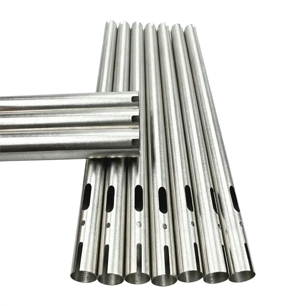
| Item | Stainless Steel Thin-Wall Open Tubes, Eight-Piece |
|---|---|
| Brand | AUNOV |
| Designing | Driven by your drawing or a physical sample – DFM notes are returned before any tooling is cut; the approved drawing is kept as the controlled master. |
| Tooling | Progressive and drawing dies are designed and built in house, so tooling lead time stays under our control, and first-article timing is measured from the tooling start date. |
| Samples | First-article samples ship with a dimensional report and material certificate, so any deviation is corrected at sample stage, and mass production is gated on that approval. |
| Materials | Carbon steel, 304 / 316 stainless steel, aluminium and brass are all held in stock; mill certificates and heat numbers accompany the first article. |
| Surface finish | The drawing selects the finish: plating, coating, anodising or passivation, with masking and laser marking available where needed. |
| Processing | Tube drawing with precision turning on critical diameters; first articles verify the whole flow before the run is released. |
| Equipment | Tube drawing lines with annealing and finish-turning cells, backed by CNC turning centres and a climate-controlled inspection room. |
| Tolerance | +/-0.02 mm on fitted diameters, +/-0.1 mm on formed ends; dimensional reports accompany the first article. |
| Delivery terms | FOB Ningbo or Shanghai, T/T with deposit and L/C for larger runs; price breaks tie to annual volume. |
Related Products

Request a Quote for This Part
Send a drawing or sketch — get material advice, tooling cost and a per-piece price within 24 hours (working days).