
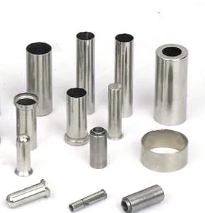
A 50mm sleeve is long enough to stop being a piece of tube and start being a component with a purpose. At short lengths, a sleeve is a shield for a sensor. At 50mm, it is a thermal buffer, a mounting boss and a pressure or contamination boundary all at once, and every one of those functions fights with the other two.
The name on the drawing says it is a sleeve for a sensor. What it actually has to do is carry a thermistor’s reading from a process environment into a housing where the electronics can survive, without either the heat nor the process finding its way back.
Length buys isolation and costs response
Extending a sleeve along the axis does two things that pull in opposite directions.
It reduces the influence of anything happening at the mounting end. Heat conducted along a metal sleeve is real: a sleeve whose base is bolted to a warm manifold will carry that warmth all the way to the tip, and at 50mm the tip temperature is no longer purely a function of the process. In a short sleeve, the base is close enough to the tip that the whole thing tends toward the process temperature and the error is small. In a long sleeve, the base is far enough away to matter and the error becomes a function of the mounting.
It also increases the thermal mass proportionally to length, and thermal mass is what sets the lag. A 50mm sleeve of the same diameter and wall as a 15mm sleeve has more than three times the mass, so it responds more slowly for the same conductance to the environment. If the process is fast-changing, the long version reads the average of the recent past rather than the present.
There is a useful design consequence here. If the long sleeve is thermally anchored at its base, the base anchor behaves as a heat sink on the measurement. The first question for a 50mm sleeve is therefore not “what is the diameter” but “what is the base temperature relative to the process”. If they are close, length is free. If they are not, the length has to be paid for in either insulation or a longer element.
Mounting decides the error more than the sensor does
A sleeve that ends in a thread, a flange, a compression fitting or a weld boss has, at that junction, a thermal path directly into the process fluid or into the pipe wall. This path is not thermal isolation — it is a shortcut.
The standard fix is a deliberate neck: a length of reduced diameter, or a reduced section of reduced wall, between the sensing zone and the mounting face. The neck works as a thermal resistance in series and it drops the temperature gradient along the sleeve. The longer and thinner the neck, the better the isolation, and the trade-off is mechanical strength and the time constant of the neck itself.
The mounting detail that matters is how the sleeve is held. Consider three arrangements for the same 50mm sleeve:
- Compression fitting with an olive. Conductive metal-to-metal contact from the sleeve into the fitting body, straight into the pipe. Excellent mechanical seal, poor thermal isolation, and the fitting body becomes part of the thermal path.
- PTFE / polymer ferrule. The sleeve is clamped without a conductive path into the housing, so the base is thermally floating. Good isolation; the ferrule’s creep becomes a long-term sealing question at temperature.
- Welded boss with a root fillet. The strongest and the worst thermally, because the fillet is a stress raiser and the weld is a metallurgical discontinuity in a pressure boundary. It also puts the sensor’s mounting stress into the same place as the fatigue load.
On a part this length, the mounting arrangement should be specified on the same drawing as the sleeve, not left to the assembly drawing, because it determines whether the sensor works.
Weld or draw: this length changes the process route
A 50mm sleeve is long enough that the forming method has to be chosen deliberately.
A drawn tube is made by pulling, and every pass through the die reduces both the diameter and the wall. For a long, thin-walled sleeve, achieving a 50mm length by drawing means drawing the tube longer and cutting it, which is fine — but it means the entire sleeve shares the wall thinning history of the draw. On a thin wall, the tolerance band on that thinning applies to the whole 50mm, not just to an end.
A fabricated sleeve — formed, welded and finished — allows the length to be independent of the wall, but introduces a longitudinal seam. For a pressure boundary, that seam is a weld that has to be fully penetrated, radiographically or at least pressure-verified, and it is the reason a fabricated sleeve in stainless steel usually shows up in NDE requirements.
For a non-pressure sleeve that sits in a thermowell, the fabricated route is often more economical at 50mm. For a pressure-retaining one, the drawn route avoids the seam entirely and is usually the only acceptable answer. Which one applies is a question about what the sleeve contains, and it should be answered before the material is chosen, not after.
The inside of the sleeve is a surface that has to be specified
This is routinely forgotten. The bore of a sleeve is either in contact with the sensor, or it is the space the sensor occupies, and it behaves differently depending on which.
- In thermal contact. The bore needs a defined clearance band and a defined filler. Loose fit plus air gap means the sensor reads air inside the sleeve, not the process.
- Insulating the sensor. The bore then becomes a dielectric requirement. Stainless Steel is a conductor, so an insulating element cannot touch the wall directly; a sleeve liner or a coated bore is needed, and the coating’s thermal resistance becomes part of the sensor’s calibration.
- Filled with potting. The fill has to be specified for thermal conductivity after cure, for its shrinkage, and for its temperature rating — because the fill is what holds the sensor in position for ten years.
On a long sleeve, the internal condition can also vary along the length: a sensor inserted only part way sees a different environment at the tip than one inserted fully. If the drawing does not define the insertion depth and the internal medium, the same part can legitimately be assembled two ways and read differently.
What long lengths do to tolerance on the outside
Straightness over 50mm is a real inspection item and a real manufacturing cost. A sleeve that is straight enough at 15mm can bow visibly at 50mm, and a bowed sleeve that must slide into a thermowell will bind.
The failure mode to watch is not the mean bow but the local deviation, because what matters for fit is the maximum deviation over the insertion length. Specify straightness as a maximum deviation over a stated length, not as a general straightness figure, and check it on a granite plate or in a fixture rather than by eye.
Coaxiality of the bore to the outside surface matters for the same reason and for the sealing face. If the bore is offset from the OD, the wall is thinner on one side, and on a thin-wall part that can be the whole wall tolerance in one direction.
Questions worth asking on a 50mm sleeve drawing
- Is the base mounting thermal condition defined — bolted, welded, or floating in a polymer? Without that, the achievable accuracy cannot be stated.
- Is there a defined thermal neck between the sensing zone and the mounting face, with its length and diameter called out?
- Is the length achieved by drawing or by fabrication and welding, and if welded, what NDE applies to the seam?
- Is the internal condition defined — clearance band, filler material, or insulation — along with the sensor insertion depth?
- Is straightness specified as a maximum deviation over the insertion length?
- Is bore-to-OD coaxiality specified, given that a thin wall makes wall thickness depend on it?
- Does the sleeve carry pressure, and if so where is the pressure boundary drawn and how is it verified?
That last one deserves emphasis. A “sleeve” on a drawing carries no pressure connotation at all, and a buyer can reasonably assume it does not. If it sits across a process line, the drawing must say so, because a sleeve that is only meant to be a mounting boss and a sleeve that is meant to hold pressure differ by an entire order of magnitude in wall, seam requirement and test method.
This part belongs to our Deep Drawn Tubes & Sleeves range. The deep drawn tubes & sleeves pages collect the process notes, common materials and inspection points behind every product in the family.
Specifications
| Item | Stainless Steel Closed Tubes and Flange Rings Assortment |
|---|---|
| Brand | AUNOV |
| Designing | Quotation follows the print, not a catalogue – unusual walls, threads or tolerances are feasibility-checked first; the same drawing is used for every repeat order. |
| Tooling | Die design and toolmaking stay in house, so the die charge appears as its own quotation line, and the die remains dedicated to your part. |
| Samples | Sample parts are measured and reported before submission, so the sample is retained as the master, and later batches are gauged back to the signed sample. |
| Materials | Stainless Steel 304 and 316L, pickled and annealed, 50 mm nominal wall – one grade chosen for corrosion duty and formability of this sleeve. |
| Surface finish | Plating, coating or polishing to suit the drawing; finish thickness and adhesion checked on the first article. |
| Processing | Drawn-tube process with in-line annealing and finish turning; batch records are filed so a repeat order starts from approved data. |
| Equipment | Tube drawing benches with in-line annealing furnaces; secondary ops run on CNC turning centres, inspection on the CMM. |
| Tolerance | +/-0.05 mm on bore, wall thickness band confirmed at first article; capability is checked on the first article before the run continues. |
| Delivery terms | Terms are FOB by default, with CIF and DDP quoted on request and freight priced to your door. |
Related Products


Request a Quote for This Part
Send a drawing or sketch — get material advice, tooling cost and a per-piece price within 24 hours (working days).