
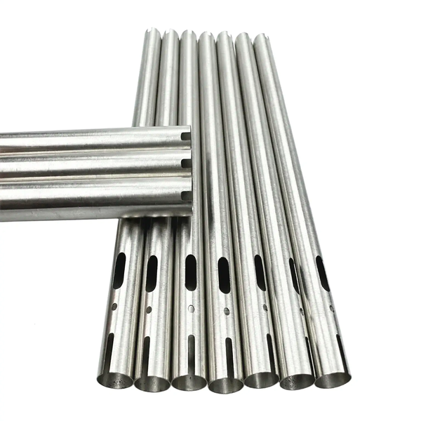
Slots cut into the end region of a drawn tube turn it into something else entirely – spring fingers, strain-relief legs, clamp petals – and that is exactly the job of the slotted stainless steel precision tubes covered here. This page gets concrete about how the slots are produced, what they do to end roundness, and the burr discipline that decides whether the fingers flex a thousand cycles or crack on the tenth.
Piercing slots in-die versus laser cutting: where the cost crosses over
There are two production routes for slots in a drawn tube end, and choosing between them is a volume decision made with real numbers. Laser cutting plots the slot path with a focused beam: no hard tooling, infinite geometry freedom, per-part cost that barely moves from part one to part ten thousand. Piercing slots in a dedicated die – the tube end positioned over a slotted mandrel, a punch pressing the slot shape through the wall – carries tooling cost on the front end and a per-part cost that falls to a small fraction of laser time.
In our quoting history the crossover sits near 3,000 to 5,000 parts for typical finger patterns: below that, laser wins on total program cost; above it, the die amortizes quickly and also buys three things laser cannot:
- Burr control by design. A properly maintained pierce die shears the wall between matched cutting edges, leaving a burr measured in hundredths of a millimeter; a laser leaves recast dross that must be removed mechanically anyway.
- Repeatable slot location. The die locates off the tube OD and a positive end stop, so slot pitch is as stable as the tooling, whereas every laser part re-establishes its datum optically.
- Cycle economics on tapers and mixed slots. A die can pierce all slots in the end in one hit, including different widths in the same pattern, which laser must trace serially.
The honest boundary on piercing is slot width versus wall thickness. Below a slot width of about 1.5 times the wall, punch pressure concentrates and the slug control gets fussy – we recommend laser below that ratio and say so in the review rather than selling a die that will fight its own maintenance.
Slot geometry and the spring-finger function it has to deliver
A slotted tube end is usually a spring, and the spring rate lives in three dimensions on the print: slot width, finger width between slots, and the finger length from the slot root to the tube end. The stiffness of a cantilever finger scales with the cube of its effective length and the cube of its thickness – small geometry errors are large stiffness errors. A finger 0.3 mm too wide at the base is measurably stiffer; a slot 0.2 mm short makes the finger act as if it were thicker. When the assembly is a connector that must grip a mating pin with a defined normal force, these are not decorative tolerances.
We ask customers to state the function numerically when they can – insertion force target, retention force target, number of cycles – because it lets us work the geometry backwards. A grip force of a few newtons on a 2 mm pin with 300-series stainless steel fingers points to finger widths of 0.6 to 1.0 mm at typical 0.3 to 0.5 mm walls, with slot roots radiused rather than square. The radius is the difference between a spring and a crack initiator: stress at a sharp slot root in half-hard stainless steel runs several times the nominal, and fatigue failures on slotted ends almost always start at an unradiused corner.
Slot root radius is a tooling decision and a drawing note. In pierced slots, the punch corner carries the radius to the part; in laser slots, the radius is programmed into the path. Either way, we default to a root radius of at least 0.2 mm or 0.5 times the wall, whichever the geometry allows, and we flag any print that asks for square slot roots on a cyclically loaded part.
End roundness after slotting: the springback conversation
Cutting slots removes hoop continuity, and the tube end reacts immediately: the remaining fingers spring outward slightly as the residual compressive stress from drawing is released, typically 0.05 to 0.15 mm of diameter growth at the end depending on wall and material temper. The tube body holds its round, but the slotted zone does not, and an assembly that expects the slotted end to pass into a round housing needs that growth accounted for.
Three handling rules follow from this, and we build them into the routing. First, gauge and inspect the slotted end at a defined plane – our standard is 1 mm inboard of the slot root and at the extreme end – because a single diameter mid-finger misses both failure modes: inward dents and outward growth. Second, no secondary forming operation after slotting unless it is designed for the slotted geometry; a rolling or sizing pass intended for a solid tube will bend fingers unpredictably. Third, packaging supports the body, never the fingers: a finger bent in transit cannot be bent back without a visible work-hardened witness line that becomes the fatigue origin.
Where the design needs the slotted end to hold a close fit, the option worth pricing is a light post-slot sizing pass over a tapered mandrel that sets all fingers to a uniform reference diameter. It costs one more operation and saves a sorting conversation at assembly, and whether it belongs on the routing is a drawing-level decision we surface in the manufacturability review.
Burr discipline where the part flexes
On a static part, a burr is a cleanliness problem. On a flexing finger, a burr is a crack that has not finished happening yet. The slot edge sees a bending stress reversal on every cycle, and a burr fold at that edge is a pre-existing defect with a stress concentration at its root. Slots produced by laser carry their own version of the same problem: recast dross on the cut edge, a thin re-solidified layer with different microstructure and residual tension, which is why we mechanically finish laser-cut slot edges on any part with a cycle requirement rather than shipping them as-cut.
Our edge finishing sequence for slotted ends is deliberately low-tech and tightly controlled: abrasive-filled brushes or very fine belt passes along the slot edges, followed by a 10x visual inspection for fold-overs, followed by a tape test on the sample plan – a strip of tape pulled across the slot edge should come away clean, and a burr that catches tape will catch a fatigue cycle. Both edges of every slot get this treatment; the inner edge, the one nobody sees, is the one that fails.
We also state a deburr acceptance number on the inspection plan – edge break within 0.05 to 0.1 mm, no measurable burr height above 0.03 mm on the sample plan – because “deburred” without a number deteriorates silently over a production run as brushes wear. Brush condition is checked and logged per shift on slotted-end work, which is a small cost that prevents the classic slow drift from good parts to rejected lot.
How we verify slot pattern, edges and end geometry on every lot
Verification on slotted tube ends is anchored to the signed first article and runs per lot as follows:
- Slot dimensions – width and position measured optically on the sample plan against a projected overlay or on the CMM, with slot pitch checked as a cumulative dimension across the pattern, not only slot-to-slot.
- Slot root condition – root radius confirmed on the first article at magnification, and production parts checked for the absence of corner cracks and fold-overs at 10x minimum.
- Finger width – measured at the root and at the tip, because taper within a finger is a stiffness defect the slot dimensions alone will not reveal.
- Edge finish – tape-test on the sample plan, burr height limit of 0.03 mm, brush-condition log reviewed per shift.
- End roundness – two-axis diameter at the defined planes with finger-tip growth recorded, so springback stays inside the housing fit band.
- Function sample – where the customer states insertion or retention force, a sample of finished parts is force-tested against a gauge pin of the mating diameter, and the force band is archived with the lot under our ISO 9001 records.
Bring the mating part or its gauge dimensions to the quotation, and the slotted end will be designed, tooled and verified against the force the assembly actually needs rather than a geometry that merely looks right.
Deep Drawn Tubes & Sleeves is the parent range for parts like this one; the overview page gathers the tooling logic, finishing options and tolerance notes that apply across the family.
Specifications
| Item | Stainless Steel Precision Tubes with Slotted Cut Ends |
|---|---|
| Brand | AUNOV |
| Designing | Send the drawing, or a sample we can measure, you get a DFM review together with the quotation. |
| Tooling | Tooling designed and cut in house, with your part number on the tool record. |
| Samples | Pre-production samples of the tube ship with a full dimensional report and material certification. |
| Materials | 304 / 316 stainless steel is the primary stock for this part, alongside carbon steel (SPCC / DC01), aluminium, brass and copper, with the final grade confirmed at the drawing review. |
| Surface finish | Plating, e-coat, powder coating, anodising or passivation as the drawing calls out, per your print. |
| Processing | Progressive deep draw stages with in-line annealing as the draw ratio demands, with piercing and finish machining under the same roof. |
| Equipment | Our press floor runs 5-250 T mechanical and 250-500 T hydraulic presses, in-house CNC cells and a temperature-controlled inspection room. |
| Tolerance | +/-0.1 mm on as-drawn surfaces and +/-0.03 mm on machined surfaces. |
| Delivery terms | FOB standard, DDP offered for EU and US, payment T/T or L/C, D/P for repeat accounts, call-off schedules and blanket orders supported. |
Related Products


Request a Quote for This Part
Send a drawing or sketch — get material advice, tooling cost and a per-piece price within 24 hours (working days).