
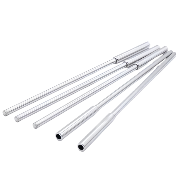
Holding a 0.2 mm wall on an 8 mm tube is a drawing-process problem before it is a tolerance
“Thin wall” on a precision tube is not a marketing word – it is a ratio, and the ratio decides the process. A 0.2 mm wall on an 8.0 mm outside diameter is a wall-to-diameter ratio of 1:40, and at that ratio the tube no longer behaves like a machined cylinder. It behaves like a membrane that happens to be round: it dents under finger pressure, it ovalises in a V-block, and its measured diameter depends on how hard the micrometer anvil is squeezed. We produce these tubes in 304 and 316 stainless steel by cold drawing over tooling, with drawing anneals between passes, and the drawing plan – not the inspection plan – is what actually holds the wall.
A common drawing-office habit makes this worse: specifying a thin-wall tube the way a thick-wall tube would be specified, with OD, ID and wall all toleranced independently. On a 0.2 mm wall a +/-0.05 mm band is half the wall, and when OD is turned to size while the wall floats, the bore floats with it. The first thing our manufacturability review does with a thin-wall enquiry is ask which of the three dimensions is functional:
- If the tube slips over a mandrel or pin, the bore is functional. We hold the bore with a plug mandrel and let the OD absorb the wall variation.
- If the tube fits a housing bore, the OD is functional and we draw the OD over a die, opening the bore tolerance.
- If fluid volume or pressure matters, the wall is functional, and we hold it by measuring destructively at the ends and controlling the middle through the drawing schedule.
Floating-plug drawing and where the wall thickness is actually decided
A thin-wall stainless steel tube is drawn over a cylindrical plug or, on long lengths, a floating plug that rides in the deformation zone held by friction and geometry. The plug sets the inner diameter, the die sets the outer, and the difference is the wall. What the drawing office often misses is that the wall is set at the die land, and everything upstream – the incoming wall, the reduction schedule, the anneal – only sets the conditions under which that happens.
Our schedule for a typical 8.0 x 0.2 mm 304 tube from 12.0 x 1.0 mm stock runs four to six passes with an intermediate bright anneal, each pass reducing area by 20-35 percent. Above roughly 40 percent area reduction on thin-wall 304 the tube seizes on the plug and scores the bore; below 15 percent the pass costs money without buying uniformity. The window between those is the process window, and our schedules stay in the middle of it with margin for stock variation – because mill-certified 1.0 mm wall stock is itself +/-10 percent on the wall, and a schedule with no margin turns incoming stock variation directly into outgoing wall variation.
What this means on your drawing: a wall called out at 0.20 +/-0.02 mm is realistic on this process. A wall called out at 0.20 +/-0.01 mm across a 300 mm length is a request for a different process – machined or honed – and the quotation will say so rather than quietly shipping a drawn tube that misses it half the time.
Ovality and concentricity are different defects on a thin wall
Roundness on a thin-wall tube is where measurement and manufacturing genuinely diverge, so it is worth separating the two roundness defects that get conflated on drawings:
- Ovality is the difference between the largest and smallest diameter at one cross-section. It comes from handling, die exit condition, and coiling or straightening, and it is elastic – an ovalised section springs back toward round under internal pressure or a round gauge.
- Eccentricity is the offset between the bore centreline and the OD centreline. It comes from the drawing process – a plug that sat off-centre, or eccentric stock – and it is geometric: no amount of annealing or handling fixes it. On a 0.2 mm nominal wall, an eccentricity of 0.05 mm makes the thin side a 0.15 mm wall, and the burst pressure on that side just dropped by a quarter.
We control eccentricity by rotating the tube a quarter turn between drawing passes where the schedule allows – successive passes from different rotational starts average out incoming stock eccentricity rather than faithfully reproducing it. We measure it at two planes near each end and one mid-length, by sectioning on samples or, non-destructively, by ultrasonic wall mapping on lot samples. Ultrasonic wall mapping is the method we recommend for any thin-wall tube that will see pressure: it walks the whole circumference and the whole length, and it finds the thin place a two-point micrometer reading averages away.
One measurement warning worth passing on: a two-point micrometer on a 0.2 mm wall reads high if the anvil force exceeds about 5 N, because it flattens the tube slightly between the anvils – our floor specifies gauge force in the inspection instruction, because a hard-squeezed micrometer has certified more thin walls than any drawing process ever thinned.
Annealing cycles, and what cold work does to a 304 tube before you weld it
304 is austenitic, which means it cannot be quenched to hardness – but it work-hardens enthusiastically, and a drawn tube is a heavily cold-worked tube. A 304 tube that has taken 70 percent total cold reduction without an intermediate anneal has a tensile strength pushing 1200 MPa, a residual stress field that will move the tube when you cut it, and almost no ductility left for any later flaring, bending or bulging. Every thin-wall tube we deliver passes through bright annealing – hydrogen or vacuum atmosphere, no pickling, no scale – and where the anneals sit in the schedule is a real engineering decision:
- Anneal before the last pass leaves the tube half-hard with 15-25 percent cold work – the condition to specify if the tube will be bent, flared or rolled into a header, because full-soft thin walls wrinkle in bending.
- A final solution anneal (1050 degrees C, rapid cool) gives the soft, dimensionally relaxed condition for deep subsequent forming or maximum corrosion resistance, at the price of a tube that must be handled on supports rather than gripped.
- Chloride service changes the plan. Heavy cold work in 304 can sensitise it to stress-corrosion cracking, and a heavily drawn thin wall is exactly where transverse cracks appear in the field. If the service involves chlorides above roughly 25 ppm at elevated temperature, we want to know at quotation: the answer is a final solution anneal and a lower-cold-work schedule – not the cheapest drawing plan.
- Welding downstream changes the delivery condition. A tube left hard will bow 2-3 mm along a seam weld as its residual stress relieves under weld heat, so for welded assemblies we default to a stress-relieved or solution-annealed condition and quote straightness after weld – the straightness that actually matters.
Cleaning a long small bore: the specification nobody writes down
A thin-wall precision tube usually carries something through its bore – a fluid, a gas, a sensor, an optical fibre – and the bore of a drawn tube arrives carrying drawing lubricant, phosphate or oxalate film residue, and fine stainless steel debris from the die land. Outside is easy: degrease, passivate, done. Inside a 6 mm bore 300 mm long, none of that is easy, and “clean” is a word that needs a number before it can be inspected.
Our cleaning sequence is alkaline immersion with ultrasonic agitation, a hot deionised water purge, nitric or citric passivation, and a final filtered-nitrogen purge and dry. The acceptance test is not visual – you cannot see down a small dark bore – it is gravimetric: a solvent flushed through the bore is filtered and the extracted residue weighed, with the acceptance criterion we normally work to being under 5 mg per tube for hydraulic, sensor or medical-adjacent service. Three design decisions make the cleaning problem cheaper, and all of them are free to make correctly on the drawing:
- Open both ends for cleaning. A tube delivered open can be purged through; if the assembly closes one end, we clean before closing, and the drawing should say which happens first.
- Avoid ID features that trap lubricant. Grooves and steps in the bore are cleanable but each adds a dwell volume; a plain bore is the cleaner part.
- State the cleanliness class only if it is real. “Clean” costs a defined process and a defined test. If the tube just needs to be oil-free, say oil-free – it is a different and cheaper specification. And we passivate after all mechanical work: drawing leaves an iron-contaminated surface that tea-stains in humid storage even though the bulk material is fully stainless steel, and a passivated tube ships bright and stays bright.
How we verify thin-wall tubes before they leave the floor
Thin-wall tube verification is a defined sequence, run on every lot, with the acceptance criteria travelling under the part number so a repeat order is verified the way the first was:
- Wall thickness at the ends on a sectioned sample, four compass points each end, against the wall tolerance – the size measurement the drawing cares about most and the fastest process-health signal: wall drift at the ends means the schedule has moved.
- Ultrasonic wall mapping on lot samples – full circumference, full length – for any tube with a pressure or burst requirement, reporting the thin-place value, not just the average.
- OD by low-force micrometer at three stations, two directions each, with gauge force stated in the instruction so the reading is repeatable between our floor and yours.
- Bore by plug gauge or air gauge depending on size: below about 3 mm we gauge with precision plugs; above that, air gauging gives sub-micron repeatability without contact force.
- Straightness on a surface table with the tube rotated, gap read under a straight edge – method and limit both from the drawing, defaulting to 0.5 mm over 300 mm for handling-critical applications.
- Material verification by PMI on lot samples and mill certificates against the melt for the full lot.
- Bore cleanliness by gravimetric flush test on samples from any tube ordered to a cleanliness class, with the residue weight recorded on the report.
- Hydraulic proof or bubble test on order where a burst or leak requirement is stated, at the drawing’s proof pressure, held for the stated time.
First articles ship with the full dimensional report and material certificate; repeat lots run the same sequence at the same sampling. Send a drawing or a sample – the manufacturability review comes back with the drawing questions above answered, a proposed drawing schedule, and a quotation stating which dimensions we hold and which we let float.
This part belongs to our Deep Drawn Tubes & Sleeves range. The deep drawn tubes & sleeves pages collect the process notes, common materials and inspection points behind every product in the family.
Specifications
| Item | Stainless Steel 304 Thin Wall Precision Tubes |
|---|---|
| Brand | AUNOV |
| Designing | A drawing file or a physical sample starts the review, DFM feedback is returned with the quote. |
| Tooling | Every die designed and built in our toolroom, with your part number on the tool record. |
| Samples | First articles go out with dimensional data and material certification. |
| Materials | 304 / 316 stainless steel is the primary stock for this part, alongside carbon steel (SPCC / DC01), aluminium, brass and copper, with grade selection confirmed at drawing review. |
| Surface finish | Plating, e-coat, powder coating, anodising or passivation, selected against the drawing requirement. |
| Processing | Staged deep drawing with in-line annealing where needed, then pierced and CNC-machined in house. |
| Equipment | 5-250 T mechanical presses plus 250-500 T hydraulic presses, CNC turning centres, climate-controlled CMM room. |
| Tolerance | Tolerances to +/-0.1 mm as drawn, +/-0.03 mm on machined features. |
| Delivery terms | FOB standard, DDP offered for EU and US, payment T/T or L/C, D/P for repeat accounts, call-off scheduling supported. |
Related Products


Request a Quote for This Part
Send a drawing or sketch — get material advice, tooling cost and a per-piece price within 24 hours (working days).