
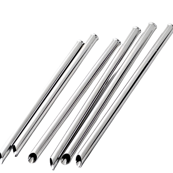
The Stainless Steel Precision Tube with Mitered Cut Ends is a drawn tube whose final geometry is made at the saw, not the press. This page covers what actually happens when a 45-degree face is cut into a thin-wall tube, the fit-up arithmetic that turns angle error into weld gap, and the end conditioning that makes a mitered joint weldable rather than merely cut.
Cutting a 45-degree face into a thin wall without collapse
A miter is the most demanding thing you can ask of a cut-off operation. The blade engages the tube wall progressively – starting as a point contact, growing to the full wall cross-section, then peeling away again – and the wall is unsupported on the exit side. On a 1.0 mm wall, that point engagement is where tubes get dented: the blade pushes before it cuts, the oval section springs, and the finished face is neither flat nor round.
The countermeasures are mechanical and boring, which is why they get skipped. We cut miters with the tube supported in a bore mandrel or a full-contact V-block sized to the OD, with the clamp positioned within 5 mm of the cut plane. On thin walls the support is internal as well as external: a slender mandrel that the blade cuts through sacrificially is cheaper than a 20 percent scrap rate on unsupported cuts. Blade selection follows the material – fine-tooth abrasive discs under flood coolant for stainless steel up to about 2 mm wall, slow-speed carbide-tipped saws above that, where the greater rigidity wins back the longer cycle time in burr quality.
Heat is the second enemy, because a mitered stainless steel tube is usually headed for a weld, and weld quality reads the heat-affected zone at the cut face. A dry, fast cut leaves a tinted, sensitized band a fraction of a millimeter deep; under flood coolant, the face stays clean and the weld starts from parent metal rather than oxide. We hold cut-face color to a “no discoloration visible” acceptance criterion because it is a proxy for a whole family of downstream problems we do not want to inherit.
Angle error and the weld gap it creates
The relationship between miter angle tolerance and joint gap is arithmetic, and it deserves to be on the drawing. Two tubes butted at a nominal 90 degrees with 45-degree miters: if one part is cut at 44 degrees and its mate at 46, the angular mismatch is 2 degrees, and the resulting gap across the joint face runs roughly 0.017 mm per millimeter of joint width. On a 20 mm diameter tube, that is about 0.35 mm of gap at the widest point – enough to demand weld filler, enough to distort the joint on tacking, enough to make a leak path if the weld sequence fights the gap instead of closing it.
We therefore quote miter angle to +/-0.5 degrees as standard, and hold +/-0.25 degrees where the fixture allows direct angular referencing. The verification method matters as much as the number: the angle is not inferred from the saw setting, it is measured on the part, with the tube seated on its OD in a sine-bar fixture or measured on the CMM in our climate-controlled room against the tube axis, not against the clamp face. The distinction sounds pedantic until the first rejection meeting, when a saw setting sheet argues with a part measurement and only one of them is evidence.
Where the miter feeds a brazed or welded assembly on your side, the number to negotiate is not the angle alone but the pair – angle and land length together define the fit-up window. We can supply mated pairs gauged against each other for critical joints, cutting the second part only after measuring the first, which halves the tolerance stack at the joint for a modest setup premium.
Keeping the end round when the cut removes half the section
A mitered end is structurally a C-section, open on one side, and it loses torsional and bending stiffness in proportion to how much material is gone. Handling a mitered tube by the mitered end – dropping it point-first into a tote, pressing it into a fixture that grips near the face – will oval it, and an oval miter cannot be pushed back into shape without putting a witness crease next to the weld land.
Process discipline carries the load here. After the miter cut, parts travel in racks that support them on the cylindrical body, never on the cut face. Secondary operations that need to grip near the end use internal mandrels sized to the bore, so clamping force is reacted through the full section. And where the drawing includes a subsequent operation after the miter – flaring, beading, a rolled bead for a seal – we sequence it before the miter whenever the print allows, because forming operations are safer to run on a closed section than on an open one.
The roundness check on the mitered end is part of the standard plan: two-axis diameter measurement 2 mm behind the cut face, with ovality reported against the drawn OD tolerance. If a design genuinely needs a tight roundness band right at the miter, the drawing should say so – the default assumption elsewhere in the industry is that the region near an angular cut is exempt, and we would rather quote the effort than surprise you with a conservative interpretation.
End conditioning: from cut face to weld-ready land
A mitered face is a weld preparation, and it earns weld-pre treatment. Three conditions on the face decide whether the weld is sound: burr height, squareness of the face to the wall, and surface texture. Burr on the inner edge is the worst offender – folded inward, it obstructs flow and becomes an inclusion site; folded outward, it traps oxide under the weld root. We deburr mitered faces with a controlled edge break of 0.1 to 0.2 mm on both edges, verified by feeler and 10x inspection rather than by eye alone.
Face-to-wall squareness – the perpendicularity of the cut face to the tube’s own wall, as distinct from the miter angle to the axis – is what the weld sees as root gap variation around the circumference. A wall that is 0.05 mm out of square to the face produces 0.1 mm of gap variation around the joint, which is most of a typical root-gap budget. The saw setup controls it, and the fixture is re-qualified each shift change on miter work with a test cut that gets measured, not admired.
Finally, cleanliness is a specified state, not an aspiration: mitered parts get a solvent wash and a lint-free dry after deburring, and they ship with end caps on the mitered side. The cap does double duty – it protects the thin land edges from transport nicks and keeps shop dust out of the bore between our dock and your weld cell.
How we verify angle, land and edge condition on mitered tube
Each mitered-tube lot ships only after these named checks, run against the signed first article:
- Miter angle – measured on the part in a sine fixture or on the CMM against the tube axis, per the sample plan, with the angle logged for every first-article part.
- Land width and face flatness – the joint face checked for flatness and full-wall presence at a minimum of four circumferential positions, so a partially-cut or chipped land cannot pass a single-point check.
- Edge condition – edge break confirmed at 10x minimum on both inner and outer edges; burr height over 0.05 mm is a reject, not a negotiation.
- Cut-face color – visual acceptance criterion of no discoloration, as a proxy for heat input at the face.
- Roundness behind the cut – two-axis OD measurement 2 mm behind the face, ovality reported against the drawn tolerance.
- Traceability – material certificate, fixture qualification record, and per-lot inspection sheets filed against the part number in our quality records, with reorders measured back to the signed master.
Send the joint requirement – weld process, root gap target, mating part geometry – with the tube drawing, and the quotation will come back with the angle, edge break and pairing options priced as deliberate choices rather than defaults.
This part belongs to our Deep Drawn Tubes & Sleeves range. The deep drawn tubes & sleeves pages collect the process notes, common materials and inspection points behind every product in the family.
Specifications
| Item | Stainless Steel Precision Tubes with Mitered Cut Ends |
|---|---|
| Brand | AUNOV |
| Designing | A drawing file or a physical sample starts the review, our engineers reply with a manufacturability assessment and pricing. |
| Tooling | Our own toolroom designs and builds every die, with your part number on the tool record. |
| Samples | First articles go out with dimensional data and material certification. |
| Materials | 304 / 316 stainless steel is the primary stock for this part, alongside carbon steel (SPCC / DC01), aluminium, brass and copper, with the final grade confirmed at the drawing review. |
| Surface finish | Finish options: plating, e-coat, powder coating, anodising or passivation, selected against the drawing requirement. |
| Processing | Staged deep drawing, with in-line annealing where the draw ratio requires, then pierced and machined in house. |
| Equipment | Press capacity from 5 to 500 T across mechanical and hydraulic lines, CNC turning centres, climate-controlled CMM room. |
| Tolerance | As-drawn tolerance +/-0.1 mm, machined features held to +/-0.03 mm. |
| Delivery terms | FOB standard, DDP offered for EU and US, T/T or L/C, D/P on repeat business, scheduled call-offs welcome. |
Related Products

Request a Quote for This Part
Send a drawing or sketch — get material advice, tooling cost and a per-piece price within 24 hours (working days).