
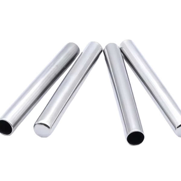
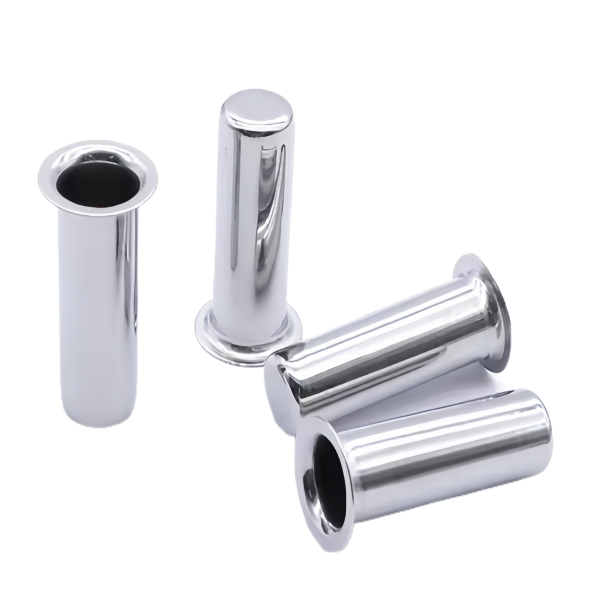
The Chrome Plated Drawn Steel Round Tube Sleeves pairs a seamless drawn shell with a hard chrome layer on the working bore – a combination that only works when the plating is treated as a dimension of the part, not a coat of paint applied at the end. This page covers where the chrome actually goes inside a drawn sleeve, how the bore is prepared to receive it, and the acceptance checks that keep a shaft sleeve sliding instead of seizing.
Plating build-up inside a drawn bore and why it is not uniform
Chrome plates preferentially on edges and outside corners, and it plates reluctantly in recesses and internal surfaces – a drawn sleeve bore is an internal surface from the anode’s point of view. The current density at the bore wall falls off with depth, so an unmanaged bath would leave the mouth of a long sleeve thick and the mid-length thin. We plan for this rather than discover it: the part is racked with conforming or internal anodes on bores deeper than about twice their diameter, and the bath chemistry, temperature and current density are tuned so the throw into the bore meets the thickness floor along the full engagement length.
- On a typical sleeve we hold a bore deposit in the 5-20 µm band against the drawing call-out, and the first article is sectioned or gauged at mid-bore, not just at the mouth, because mid-bore is where the deposit runs thinnest.
- Edge effect at the sleeve mouths is controlled with shields and robbers on the plating line; without them the mouths build a heavy lip that closes the bore by more than the deposit thickness alone.
- Thickness on the OD is verified too where the OD carries a fit – chrome does not respect the print’s distinction between inside and outside.
The practical consequence for your drawing: a chrome-plated bore call-out should specify minimum thickness and a final diameter, not a target thickness alone. Thickness that cannot be measured at the functional point is a number, not a specification.
Pre-plate machining: spending tolerance where the chrome will land
The sleeve is drawn to buy the envelope cheaply, then the bore is machined on our CNC turning centres before plating – and this is where the tolerance structure earns its keep. The as-drawn bore holds around ±0.1 mm; a sleeve that must guide a shaft needs a bore an order of magnitude better than that, so the pre-plate bore is machined to a negotiated target that leaves exactly the deposit allowance.
- We machine the pre-plate bore to the final diameter minus the planned deposit on the mean, holding the pre-plate operation to roughly a quarter of the final tolerance budget, so plating variation lands inside the band instead of eating it.
- Where the bore is short and the print allows it, we machine after plating instead – grinding or turning the chrome to size, which converts a thickness-controlled process into a diameter-controlled one at the cost of an extra operation. We quote both routes when the geometry qualifies; the choice is a cost decision the drawing can force either way.
- The datum chain is fixed: bore machined and plated against the drawn OD reference, so concentricity measured on the finished part reflects a real stack, not two independent operations that happened to be close.
This is also why we ask what the sleeve does. A spacer sleeve tolerates a generous bore; a shaft guide running at speed does not, and the difference between the two is a different machining plan with a different price attached.
Hydrogen management on plated carbon-steel sleeves
Plating is an electrochemical process, and carbon steel picks up atomic hydrogen at the cathode surface during the chrome run. On a drawn SPCC / DC01 sleeve the risk is measurable: hydrogen diffuses into the wall, and if the part is later loaded – pressed into a housing, torqued against a shoulder – the trapped hydrogen can embrittle the material. Drawn thin-wall parts are less susceptible than heavy sections, but the risk is not zero and the countermeasure is cheap.
- We bake plated parts at around 200 °C within a controlled window after plating, which drives the hydrogen back out of the lattice; the bake cycle is recorded with the batch.
- Preparation steps are watched as hard as the plating itself: the pre-plate cleaning and activation cycles are what actually set hydrogen uptake, and a bath that is out of spec embrittles parts that then look perfect under the gauge.
- Where the print specifies a hardness or a bake-out requirement, that requirement is written into the process record under your part number so a reorder runs the same chemistry, not merely the same appearance.
Turning a ±0.03 mm bore into a working running clearance
A sleeve bore on the drawing is a diameter with a tolerance; in the assembly it is a clearance, and the two are related through the shaft that runs in it. We hold machined features to ±0.03 mm, which is a real and verifiable number – but the usable running clearance is that tolerance band plus the shaft tolerance plus the thermal growth of the steel-copper or steel-steel pair in service. When a customer tells us the duty, the plating and machining targets can be biased inside the band to protect the clearance that matters.
- For a steel shaft in a chrome bore at moderate speed, the assembly wants a clearance that survives both the plating thickness variation and the bore’s roundness; we therefore hold roundness and straightness of the bore, not just its diameter, and both appear on the first-article report.
- Where the sleeve runs dry or at low speed, a slightly larger mean bore costs nothing in function and buys margin against dirt in the line; where it runs flooded and fast, the target sits closer to the minimum and the surface texture of the plated bore becomes the controlling variable.
- The plated bore’s final texture is measured, not assumed: chrome as-plated can be micro-cracked and draggy, and a light post-plate finishing pass changes its friction behaviour more than a diameter shift of a few microns would.
Uniform wall as the hidden requirement in round sleeves
A round sleeve is the friendliest geometry we draw – metal flows evenly in every direction, so the wall distribution is the most predictable of any form, typically within 10-15% at the corner radius. Predictable, however, is not the same as free. A sleeve whose wall wanders around the circumference is a sleeve whose plating varies too, because the machining allowance and the deposit both inherit the drawn wall’s geography. Where a print calls a wall minimum, we hold it by planning the stage reductions rather than by hoping the anneal is kind, and the wall map at the thinnest section goes on the first-article report.
- Wall uniformity and concentricity are related but not identical: a uniform wall that is offset is concentric bad, and a centred bore over a wandering wall is uniform bad. We measure both, and the first article names which one governs.
- Where the sleeve is long relative to its diameter, straightness over length joins the named list – a bowed sleeve plates unevenly, machines unevenly and installs unwillingly.
- Cut-to-length, end-facing and chamfering follow drawing and plating per the drawing’s joining method, with lengths held to print and the end finish matched to whatever the assembly does next – brazing, welding, or simply butting against a shoulder.
How we verify a plated sleeve bore before the batch ships
The acceptance sequence below is the same for prototypes and production; only the sampling intensity changes.
- CMM first article in the climate-controlled room: bore diameter at named sections along the length, OD, and concentricity of the plated bore to the drawn OD, against your print and the signed first-article report.
- Deposit verification: chrome thickness at the functional points – mid-bore included – by the method the drawing calls for, plus adhesion evidence from the qualification batch.
- Form checks: bore roundness and straightness over the engagement length, and wall thickness at the thinnest section of the drawn shell, all recorded against the part number.
- End condition: cut ends faced, deburred and chamfered per the drawing, with bore cleanliness confirmed so no plating rack marks or swarf travel with the parts.
- Traceability: mill certificate per heat, plating and bake records, and the ISO 9001 inspection plan – the shipment file answers an auditor’s questions before they are asked.
Deep Drawn Tubes & Sleeves is the parent range for parts like this one; the overview page gathers the tooling logic, finishing options and tolerance notes that apply across the family.
Specifications
| Item | Chrome Plated Drawn Steel Round Tube Sleeves |
|---|---|
| Brand | AUNOV |
| Designing | Send the drawing, or a sample we can measure, a manufacturability review comes back with the quotation. |
| Tooling | Dies designed and built in our own toolroom, with your part number on the tool record. |
| Samples | First-article samples ship with a dimensional report and material certification. |
| Materials | Carbon steel (SPCC / DC01) is the primary stock for this part, alongside 304 / 316 stainless steel, aluminium, brass and copper, with grade selection confirmed at drawing review. |
| Surface finish | Finish options: plating, e-coat, powder coating, anodising or passivation, as called out on your print. |
| Processing | Staged deep drawing, with in-line annealing where the draw ratio requires, with piercing and finish machining under the same roof. |
| Equipment | Press capacity from 5 to 500 T across mechanical and hydraulic lines, in-house CNC cells and a temperature-controlled inspection room. |
| Tolerance | +/-0.1 mm on as-drawn features, +/-0.03 mm on machined surfaces. |
| Delivery terms | FOB as standard, DDP available for EU and US destinations, T/T or L/C, with D/P for repeat business, call-off schedules supported. |
Related Products
Request a Quote for This Part
Send a drawing or sketch — get material advice, tooling cost and a per-piece price within 24 hours (working days).