
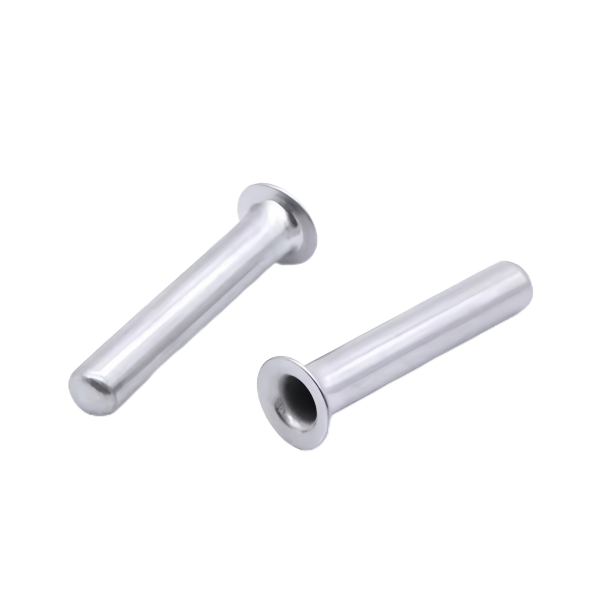
The curl gap: a semi-tubular rivet is designed to be deformed by the user
A semi-tubular rivet is the one product we make whose specification is mostly about what happens to it after it leaves our floor. The rivet’s hollow, thin-walled end – the “semi-tubular” part – exists so that the setting operation can curl it outward over the parts it joins. The rivet is a fastener that is intentionally incomplete until it is set, and its quality is measured not just as a part but as a joint: the curl has to form at the right force, roll to the right diameter, and fill the right space, or the joint is loose, cracked or torn.
The geometry that makes the curl work, and what has to be right about it:
- The curl gap – the wall thickness at the rivet’s hollow mouth. The setting punch pushes the hollow wall over a flaring anvil, and the wall rolls outward like the top of a tin can being opened. A thick wall curls stiff, needs high setting force and risks cracking as it rolls; a thin wall curls easily but may tear at the mouth instead of rolling. The gap is the single most functional dimension on the part, and we hold it to a tenth of a millimetre or better where the drawing’s joint strength requires it.
- The cavity depth. How far the hollow section runs up the shank decides how much material participates in the curl. A shallow cavity produces a short, stiff curl; a deep cavity produces a wide, soft one. Between them sits the designed joint – and the depth interacts with the grip range (the total thickness of parts joined), so a rivet family’s depth is chosen per grip, which is why rivet catalogues are organised by grip first.
- The mouth edge. A sharp inner edge at the cavity mouth is where tears start. We radius or chamfer the mouth as a forming detail, and the first-article set test tells us whether the edge is right for the material’s temper.
Wall at the rivet’s mouth decides the setting force
Setting force is where the rivet meets its customer’s production line, and the wall thickness at the cavity mouth is the variable that controls it. The relationship is not gentle: the curling force rises roughly with the square of the wall at the mouth, so a mouth wall 20 percent heavier than nominal raises the setting force by nearly half – enough to overwhelm a hand tool, stall an air hammer set at its factory pressure, or damage brittle joined parts such as ceramics or die-castings.
The force chain, from press to joint:
- The punch drives the rivet’s hollow wall against the anvil’s flaring cone, and the wall begins to roll. The initial force peaks as the wall bends past the mouth’s start radius; this first peak is the one that breaks brittle joined parts.
- The wall continues rolling outward against progressively higher resistance as the curl diameter grows and the material work-hardens – 304 hardens fast, so a stainless steel curl’s second half takes more force than its first, which is why a stainless steel rivet’s set force runs 30-50 percent above the same rivet in a softer alloy.
What we control on our side, and what the drawing should say:
- Mouth wall tolerance is a set-force tolerance. We hold the cavity’s wall to +/-0.05 mm as standard, +/-0.03 mm where the customer’s line is force-sensitive (a stated setting force on the drawing routes the rivet to the tighter schedule).
- Temper decides the base force level. A full-hard stainless steel rivet sets stiff; an annealed one curls soft but has a lower clamp. Where the customer’s tooling is marginal, a partially annealed shank with a locally softer curl zone is drawable – anneal treatments can be profiled – and the review will propose it when the stated force can’t be met any other way.
- The set test is the acceptance test. We set sample rivets in a representative joint stack and measure the set force, curl diameter and any cracking – because those three numbers, together, are the rivet’s specification made real.
Head-to-shank concentricity on a cold-headed blank
Semi-tubular rivets are cold-headed: a wire slug is struck in a die and the head forms in one blow (or two, on larger heads). Cold heading is fast, strong and material-efficient – the head’s grain flow follows the shape, so a headed head is stronger than a turned one – but it is a striking process, and the striking alignment is what sets the head’s position on the shank. A rivet whose head runs 0.05 mm off-axis is a rivet that enters its hole at a tilt, sets crooked, and leaves one side of the joint stack loose.
The concentricity realities of a headed rivet:
- The die controls the shank, the punch controls the head, and their alignment controls the concentricity. Our heading dies and punches are ground as matched sets and maintained to runout limits checked on a scheduled basis; the press’s own alignment is verified as tooling variable, not an assumption.
Cutting the cavity: punch-out burrs and the burr side that matters
The hollow end of a semi-tubular rivet is made either by a forming punch that displaces the metal into a cup (heading or extruding) or by a punching operation that actually pierces the tube wall – and on the punched route, the burr question is not cosmetic, it is functional in a specific direction. A punch-out burr forms on the exit side of the wall: the material stretches and tears last at the far surface, leaving a sharp crown of metal pointing down the bore.
Why the direction matters for a rivet:
- The curl side is the entry side of the punch in most rivet processes – the mouth the anvil flares is the side the cavity was made from, and that side comes out clean, sharp and correct as-formed.
- The burr crown sits deeper in the cavity, on the far side, where it never touches the anvil and never gets planished by the set. It hides inside the rivet until the rivet’s bore passes something – a wire, a cable, a rod, the fluid in a hollow joint – and then it shaves. A burr inside a cable-termination rivet strips the cable’s insulation strand by strand.
Two design choices make the burr question cheaper or harder, and both are worth knowing at the drawing stage:
- Formed cavities (extruded rather than pierced) have no exit burr at all, because no material was cut – it flowed. Forming is available when the cavity is a simple cup in a wall that the heading can move; it costs tooling depth and is our preference whenever the geometry allows.
Hardness and work hardening: a 304 rivet that will not crack when set
Stainless Steel 304 brings a specific paradox to rivet-making: the alloy’s work-hardening is what makes a set curl clamp hard and stay tight, and the same work-hardening is what makes the curl crack while it forms. A 304 semi-tubular rivet is engineered on the line between those two outcomes, and the line is the rivet’s metallurgical condition at the moment of setting.
The condition chain, from wire to joint:
- Wire condition. Heading-quality 304 wire arrives drawn and, depending on the source, anything from annealed to half-hard. The heading operation adds its own cold work – 30-50 percent at the head, more at the curl zone if the cavity is formed – and the wire’s incoming condition sets the starting point of that accumulation.
- In-process anneal decision. For most rivets we head directly from a moderate-temper wire and deliver the natural condition: hard head, workable shank, and a curl zone that sets stiff but sound. Where the cavity is deep or the head is aggressive, the accumulated work hardens the curl zone past the crack threshold, and an intermediate or final anneal (solution or subcritical, chosen by the needed strength) is scheduled – a soft curl zone with a hard head is drawable and is the standard remedy for set-cracking complaints.
The verification of all this is functional and simple to state:
- Hardness per zone on lot samples – head, shank, curl-zone wall – converted to a condition statement on the report, so the curl’s temper is a known quantity, not a hope.
- Set test to destruction on samples: rivets set in the representative stack, then pushed out or pulled apart, with the joint strength recorded. The set test catches cracking, incomplete curl, over-hard curl and a dozen other conditions that dimensional checks read as perfect.
- Bend-back or flare test on curl-zone samples for lot acceptance: the hollow mouth flared on a mandrel to a stated angle without cracking – the oldest rivet test in the book and still the most honest one for curl ductility.
How we verify a rivet with a section and a set test
Rivet verification runs on two instruments the catalogue parts of the trade barely use: the sectioned sample and the set test. The sequence per lot:
- Dimensional checks: head diameter and thickness, shank diameter, overall length, cavity depth and mouth ID – measured with low-force gauges and the stated fixtures, because a rivet is small enough that gauge technique is a real fraction of its tolerance.
- Curl-gap wall by section on lot samples: one rivet per lot cut longitudinally, the cavity wall measured at the mouth and mid-cavity against the drawing’s gap tolerance – the section is the only measurement that sees the gap directly, and it doubles as the burr-condition inspection at the punch exit zone.
- Head-to-shank and cavity-to-shank runout by V-block rotation on lot samples, against the drawing’s stated runout or our standard where the drawing is silent.
- Hardness per zone on samples: head, shank and curl-zone wall, converted and reported as the temper statement.
- The set test: samples set in a joint stack of the customer’s stated grip, on the matched anvil form we supply with the first article. Set force measured, curl diameter measured, and every set examined for cracks or tears – this is the rivet’s functional acceptance and it is run on every lot.
- Joint strength on samples: set rivets pushed out or pulled to failure in the fixture, the strength recorded and reported against the joint requirement where the drawing states one.
- Flare or bend-back test on curl-zone samples for ductility acceptance – the mouth flared to the stated angle, no cracking.
- Material and condition certificates: the wire’s mill certificate with the melt analysis, the heading and anneal records from the traveler, and the lot’s dimensional, section, hardness and set-test report shipped together – so a keg of rivets arrives with its evidence, not just its label.
Send the drawing, a joint sample, or the joined assembly itself. The review that comes back with the quotation states the curl gap we will hold, the cavity route (formed or pierced, and the deburr plan), the temper plan with the environment it assumes, the anvil form we will match, and the set-test acceptance criteria – which is to say, the whole rivet: the part, the tool that sets it, and the joint it makes.
Deep Drawn Tubes & Sleeves is the parent range for parts like this one; the overview page gathers the tooling logic, finishing options and tolerance notes that apply across the family.
Specifications
| Item | Stainless Steel Semi-Tubular Hollow Rivets |
|---|---|
| Brand | AUNOV |
| Designing | Send us your 2D drawing, or mail a sample for measurement, DFM feedback is returned with the quote. |
| Tooling | Tooling designed and cut in house, held and maintained under your part number. |
| Samples | The first-article set ships with a dimensional report plus material certs. |
| Materials | Stock for this part leads with 304 / 316 stainless steel, alongside carbon steel (SPCC / DC01), aluminium, brass and copper, per the drawing. |
| Surface finish | Zinc, nickel or chrome plating, e-coat, powder coat, anodising or passivation, per your print. |
| Processing | Staged deep drawing, with in-line annealing where the draw ratio requires, pierced and finish-machined on the same floor. |
| Equipment | Mechanical presses 5-250 T, hydraulic presses 250-500 T, CNC turning and milling cells, a climate-controlled CMM room. |
| Tolerance | Tolerances to +/-0.1 mm as drawn, machined features held to +/-0.03 mm. |
| Delivery terms | FOB is standard; DDP offered for EU and US, T/T or L/C, D/P on repeat business, scheduled call-offs welcome. |
Related Products



Request a Quote for This Part
Send a drawing or sketch — get material advice, tooling cost and a per-piece price within 24 hours (working days).