
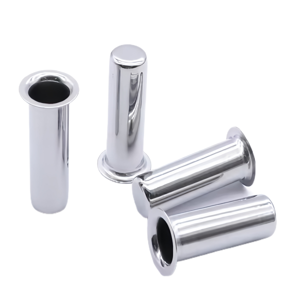
The flange-to-wall blend radius is where this part lives or dies
A deep drawn flanged sleeve is a two-zone part: a cylindrical wall, and a flange that was flat blank and became a disc sticking out sideways. Between them is the blend radius, and on this part that radius is not a styling choice – it is the highest-strain, thinnest-wall, most-likely-to-crack feature on the whole component. The material that forms the flange flows around that radius twice, once turning outward into the flange plane and once being held while the flange planishes flat, and every failure mode this product family has lives in that quarter of a circle.
The three failures, in the order we actually see them:
- Circumferential splitting at the blend. The wall thins as material bends and unbends around the radius; on a sleeve drawn from 1.0 mm stock, a tight 1.0-1.5 mm blend radius can thin the wall 12-18 percent at the tangent, and a wall that went in at 1.0 mm comes out locally at 0.85 mm. If the drawing calls a uniform minimum wall, the blend is the place it is missed.
- Wrinkling in the flange. The flange is formed by pushing material radially outward from the wall, in compression. Without enough blank-holder pressure the flange wrinkles like a pie crust edge, and the wrinkles iron out into waviness the chrome later highlights like a topographic map.
- Thickening at the flange rim. The opposite failure: too much blank-holder, and the flange material cannot flow, so it thickens and work-hardens at the rim instead. The flange rim finishes a few hundredths oversize and the flange thickness varies around the circumference, which matters the moment the flange seats on a shoulder.
The radius itself deserves a number in every quotation conversation. We hold blend radii at a minimum of 4-6 times stock thickness on drawn flanges – so on a 1.0 mm sleeve, a 4-6 mm blend – because below that the thinning stops being manageable and the splits start. When a drawing arrives with a 2 mm blend on a 1.0 mm wall, our review comes back with the thinning prediction attached and usually a proposed radius change, because moving the radius is free at the drawing stage and expensive at the press.
Draw ratio and the number of draws behind a flanged sleeve
The “deep drawn” in this product’s name is a process statement with arithmetic behind it. A flanged sleeve starts as a flat circular blank, and the wall is created by drawing that blank into a die over a punch. The limit-draw-ratio rule for a first draw on low-carbon steel sits around 1.8-2.0: the blank can be roughly twice the punch diameter and still draw in one operation without splitting. Beyond that, the part needs redraws, and a redraw is not just a repeat of the first draw – it is a new tool with new clearance, a new blank-holder strategy, and usually an anneal in front of it.
Run the numbers on a representative sleeve: OD 20 mm, wall 1.0 mm, overall height 35 mm with a 32 mm flange. The developed blank is about 42 mm across. First draw ratio: 42/20 = 2.1 – just over the single-draw limit even before the flange is considered. So the practical schedule is:
- Blank and first draw to a cup around 24 mm diameter, at a ratio of about 1.75, with the punch nose radius generous because this cup only exists to be redrawn.
- Intermediate anneal to restore ductility for the redraw – on SPCC/DC01 this is a subcritical anneal, cheap and fast.
- Redraw to the 20 mm wall diameter, ratio about 1.2, which is comfortable and produces the straight, work-hardened wall the final part needs.
- Flange formation or ironing of the flange plane, depending on whether the flange is drawn outward in the final draw or planished afterward.
- Trim the flange OD to remove the wrinkled or uneven rim material – trimming is part of the process, and the blank is deliberately cut oversize to give the trim something to cut.
- Pierce or size the bore ends as the drawing requires, then chrome plate.
Wall thinning at the blend: predicting it and specifying around it
Wall variation on a drawn flanged sleeve is not scatter – it is a deterministic pattern that the drawing can either accommodate or fight. The pattern, from bottom to top on a typical sleeve:
- At the closed or cut end: the wall is close to stock thickness, preserved by the flat bottom or the cutoff.
- Along the straight wall: slightly thickened, typically 3-8 percent, because the wall ironing and the redraw put a little compression into it.
- At the blend: the thin zone, 10-18 percent below stock with a tight radius, 3-6 percent with a generous one.
- In the flange: close to stock at mid-flange, thickened up to 10 percent at the rim where compression accumulates – before trim; after trim the flange thickness is the mid-flange value and the variation collapses.
Two drawing practices make this pattern work for the part instead of against it. The first: dimension the wall where it is stable, not where it moves. A wall thickness specified on the straight section is verifiable and repeatable; the same tolerance applied at the blend makes rejects the part will never escape. Where the blend thickness genuinely matters – pressure or fatigue duty – we specify it as a minimum with a sectioned first-article measurement, and we hit it by radius selection, not by luck.
The second: use ironing deliberately. A redraw with die clearance a few percent under the incoming wall thickness irons the wall – smooths it, work-hardens it, and evens out circumferential variation. A sleeve that will be chrome plated benefits twice, because chrome deposits on the wall as-plated and an ironed wall’s Ra 0.4-0.8 finish plates out visibly smoother than an as-drawn wall’s 1.2-1.6. Ironing is a standard step on sleeves where the bore is the plated wear surface, and it is one of the few operations that improves dimension and finish simultaneously, which is why our default schedule for chrome-plated sleeves includes a sizing ironing pass even when the dimensions alone would not demand it.
Flange thickness varies with the blank holder, and nobody notices until assembly
The flange looks like the simplest feature on the part – a flat disc – and it is the one whose variation most often surprises an assembly line. The reason is that flange thickness is set by material flow, and material flow is set by blank-holder pressure and friction, both of which drift batch to batch with lubricant, stock mill batch and die wear. A flange can finish anywhere from stock thickness to stock-plus-8-percent around its circumference on an uncontrolled process, and a sleeve that seats on its flange face in a housing pocket will rock on a thick spot the way a four-legged table rocks on one long leg.
What we do about it, and what the drawing should do about it:
- Planish the flange after forming. A coining or planishing step flattens the flange between polished flat tools under press tonnage, which corrects thickness variation to a few hundredths and gives the flange face its flatness. Any flanged sleeve that seats on its flange face gets this step in our schedule, and the flatness figure we commit to is 0.05 mm or better on a 30 mm flange.
- Trim late. The flange rim is where thickness variation concentrates; trimming the rim removes the worst of it. The flange OD after trim is a machined-class dimension, and we hold it to +/-0.1 mm or better on the trim die.
- Call out the flange face as a datum explicitly – with the wall squareness to it – and the drawing and our fixture will agree on what “square” means. A sleeve with a 25 mm flange and a squareness callout of 0.1 mm is specifying an angle of about a quarter of a degree, which the planished flange meets comfortably and an unplanished one may not.
- Flange thickness tolerance honest to the process: +/-0.08 mm on a planished flange is routine; +/-0.03 mm on the flange thickness means the flange is machined after drawing, and the quotation will say so.
Chrome over a drawn corner: coverage at the blend radius
The chrome plating on this part has to live on a surface that a drawing die shaped, and the two processes have a conversation the drawing should overhear. Chrome follows current density, and the blend radius is a concave cavity from the bath’s point of view: current density there is low, so chrome deposits thinner at the blend than on the straight wall – we plan on 60-75 percent of nominal thickness at a 4t radius, less at tighter ones. The flange rim and the open end edges, being high-current zones, plate thicker than nominal, sometimes 1.3-1.5x on a sharp edge.
Specification practice that holds up:
- State the minimum chrome in the blend, accepting it as a stated fraction of nominal. We routinely commit to 12 micrometres minimum in the blend against 20 nominal on the wall, at radii of 4t and above.
- Break the edges the plating will sharpen. The flange rim and the sleeve mouth plate thick and brittle at sharp edges; a 0.3-0.5 mm edge break before plating makes the edge deposit controllable and the flange rim dimension stable.
- Decide the bore’s fate explicitly. A drawn sleeve’s bore can be plated or left bare, and the decision is a length-to-diameter calculation – on a deep sleeve, a bare machined bore plus plated OD is the robust answer, and it is the one our review proposes when the bore plating will not meet a stated minimum.
- Bake after plate. The cold-worked drawn wall is exactly the microstructure hydrogen likes, and the post-plate bake window is on the traveler and the certificate.
How we verify the blend, the flange and the plating together
Verification on this part family is a sequence, because the features interact – the blend carries the wall minimum, the flange carries the datums, and the plating carries the dimensions the mating parts actually touch:
- Sectioned first article: one sleeve cut through the axis, wall thickness measured at bottom, wall, blend tangent and flange, against the drawing’s wall minimum and flange tolerance. This single section tells us the draw schedule, the blank holder and the planish are all in their windows.
- Dimensional report on the pre-plate part: OD, bore, flange OD and thickness, flange flatness on the surface plate or CMM, squareness of wall to flange, blend radius verification by section or radius gauge.
- Post-plate thickness mapping: XRF or magnetic readings on the wall, flange face, flange rim, sleeve mouth, and the blend – with the blend minimum reported separately against its stated minimum.
- Post-plate dimensions on the functional features: the OD and bore as the drawing’s post-plate dimensions specify, gauge force stated.
- Adhesion and appearance: burnish or impact test on samples, visual against the agreed limit sample for the finish grade.
- Bake record audited per lot – time at temperature and delay from bath – reported with the plating certificate.
- Assembly-critical pair checks where the drawing defines them: flange thickness against the mating counterbore depth, and bore against its mating fit, both reported post-plate.
This part belongs to our Deep Drawn Tubes & Sleeves range. The deep drawn tubes & sleeves pages collect the process notes, common materials and inspection points behind every product in the family.
Specifications
| Item | Chrome Plated Deep Drawn Flanged Sleeve Tubes |
|---|---|
| Brand | AUNOV |
| Designing | Share your print, or send a part to be measured, the quotation comes back with a manufacturability review attached. |
| Tooling | Dies engineered and produced in our own toolroom, each die held against your part number. |
| Samples | Pre-production samples ship with dimensional data and material certification. |
| Materials | Stock covers carbon steel (SPCC / DC01), 304 / 316 stainless steel, aluminium, brass and copper, and the grade is fixed at the drawing review. |
| Surface finish | Plating, e-coat, powder coating, anodising or passivation, per your print. |
| Processing | Multi-stage drawing, annealed in line where wall thinning calls for it, with piercing and finish machining under the same roof. |
| Equipment | Mechanical presses 5-250 T and hydraulic presses 250-500 T, CNC turning centres, climate-controlled CMM room. |
| Tolerance | Tolerances to +/-0.1 mm as drawn, with machined features to +/-0.03 mm. |
| Delivery terms | Prices FOB, with DDP for EU and US on request, T/T or L/C, D/P on repeat business, blanket orders and call-offs supported. |
Related Products



Request a Quote for This Part
Send a drawing or sketch — get material advice, tooling cost and a per-piece price within 24 hours (working days).