
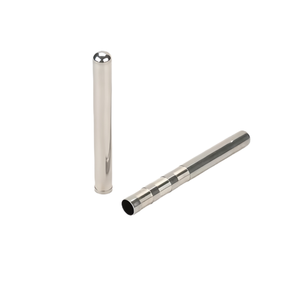
The Precision Drawn Steel Tube with Cross Drilled Holes is a drawn shell that becomes a functional part only after the holes go in. On this page we detail what cross-drilling does to a round tube, how hole position inherits the drawn-body tolerance stack, and how internal burrs are removed and proven gone when nobody can see inside the bore.
Cross-drilling both walls in one pass: the breakthrough problem
A cross hole is really two holes – entry wall and exit wall – and the second one is the difficult one. As the drill point breaks through the inner wall into the open bore, it loses its support, the drill deflects toward the path of least resistance, and the exit hole walks off position or tears a triangular breakout at the far side. On a thin wall of 0.5 to 1.5 mm the effect is at its worst: there is almost no material left to guide the point when it punches through. The industry-standard fixes are simple and non-negotiable on this part family.
First, we drill cross holes with the tube supported on a bore-filling method – a sacrificial filler rod or a drill bushing design that closes the internal space, so the drill meets the exit wall as it met the first. Filler is removed after drilling; the cost is minutes per lot and the benefit is that the exit hole lands within a few hundredths of a millimeter of the entry hole instead of visibly off-center. Second, drill geometry is matched to the work: short, stubby drills with thick webs for the small diameters typical here, run at feeds that keep the point loaded consistently rather than grabbing at breakthrough. Third, spot-drilling on the curved OD – every cross hole starts with a center or spot operation because a drill touching a convex surface at full width skates before it cuts, and skating is how hole position dies.
For patterns with several cross holes on one diameter – spacer tubes, distribution manifolds, spray tubes – we drill in one setup with the tube indexed on a dividing fixture, so all holes share a single clamping datum. Indexing between setups instead multiplies the position error once per hole, which is exactly the difference between a manifold that meters evenly and one that was never going to.
The tolerance stack from drawn OD to hole position
Hole position on this part is always declared from a datum, and the datum choice is an engineering decision disguised as a drafting habit. A cross hole is usually functional in one of two ways: as a passage aligned to something outside the tube, or as a port whose position relative to the tube’s own features matters. If the print dimensions the hole from the tube OD, then the +/-0.1 mm as-drawn OD tolerance flows directly into the hole position budget; if the hole is dimensioned from the drawn axis, the OD scatter mostly cancels but the fixture must find the axis, which is a different and more honest setup.
We work the stack with customers in the review rather than letting it be discovered at assembly. The budget in the worst realistic case runs: OD tolerance contributes up to 0.1 mm, the spot-drill walk on a curved surface another 0.02 to 0.05 mm if not spotted, and drill drift through the wall adds a few hundredths. Machined features referenced to the same setup hold +/-0.03 mm, so the concrete options are:
- Hole from OD, tube as-drawn – honest total position capability around +/-0.15 mm; fine for vent holes and non-aligning ports.
- Tube end-machined for datum, holes drilled from machined faces – position capability tightens to +/-0.05 mm relative to the machined datum; the right call when the tube seats on machined ends in the assembly.
- Alignment-critical cross holes – we offer match-drilling on assembly-relevant features or gauge-pin verification of hole-to-hole alignment through both walls, where the acceptance test is literally a pin through both holes.
Which of the three is being quoted is written into the quotation, because the price difference is real and the receiving-inspection difference is bigger.
Internal burrs: removal when you cannot reach, proof when you cannot see
Every cross hole leaves a burr where it breaks into the bore, and that burr is invisible from both ends of a long tube and unreachable by any hand tool. It is also functional: a burr at a flow port throttles the hole it belongs to, breaks free as a particle in service, and jams close-fitting components downstream. Internal burr control is the single most important process discipline on this part, and it has three layers.
Prevention first: sharp tools, supported breakthrough, and cutting parameters tuned to leave the smallest burr rather than the fastest cycle – we accept a longer drill cycle on cross-drilled work because the burr it prevents costs more than the seconds it saves. Reduction second: where the geometry permits, we scrape or ball-size the hole from inside using a bore-mounted tool, or push a slightly oversized ball through each cross hole so the exit edge is burnished flat; on bores too small for tooling, we rely on controlled abrasive flow or repeated flush cycles with filtered solvent at pressure. Proof third – and this is the step we treat as the acceptance event – a calibrated wire or pin is passed through every cross hole on the sample plan and through all holes on the first article. A hole that passes a pin of the drawing’s minimum effective diameter, from both directions, with no catch, is a hole whose burr state is proven rather than assumed.
We archive the pin size and pass direction per hole on the inspection sheet. When a customer’s cleanliness standard references particle limits, we add a gravimetric flush test on the first article: a measured volume of filtered solvent flushed through the bore is collected and filtered, and the residue is weighed and compared to the limit. It is a cheap test to run and a definitive one to have on file.
Chambers, ports and the flow area math
Many cross-drilled tubes are fluid devices – a distribution tube with a pattern of metering ports, a damper tube with bleed holes, a spacer with lightening ports – and in that role the numbers that matter are flow area and its uniformity across the pattern. A drilled hole is never a perfect cylinder: entry chamfer, drill point angle leaving a conical exit, and burr effects all trim the effective area. As a working rule, an unchamfered drilled hole delivers around 90 to 95 percent of its nominal area, and the scatter between holes in one pattern is what decides whether the assembly meters evenly.
Two practices keep pattern uniformity inside engineering bounds. One is drilling all holes of one pattern with the same tool in the same setup, so tool wear shows up as a slow drift we can catch at inspection rather than hole-to-hole randomness. The other is chamfering the OD entry consistently – chamfers sized for tool centering rather than flow tuning – so the entry condition does not vary with the curved surface. Where a customer specifies an effective-area tolerance per hole, we prove it hydraulically on the first article: each port is flow-tested in sequence, and the report lists per-port flow rather than a single average, because averages hide exactly the outliers that cause uneven distribution.
Cost note worth having early: hole count drives price almost linearly, but hole size barely does. A pattern of eight 2 mm holes costs nearly the same to drill as eight 3 mm holes, while going from eight holes to sixteen does not merely double drilling time – it doubles burr-proving effort too. Patterns with many small holes are where the filler method and indexed setup really earn their keep.
How we verify cross-hole position, alignment and cleanliness per lot
Every cross-drilled lot ships with a verification file tied to the signed first article; the named checks are:
- Hole diameter – pin or plug gauge at the drawing tolerance on the sample plan, with a note of gauge direction so entry and exit conditions are both covered.
- Hole position – optical or CMM measurement from the declared datum on the first article and sample plan, reported per hole for patterns of up to twelve holes, and as a first/last/random scheme on denser patterns.
- Alignment through both walls – a pin pass through entry and exit walls together on the first article for every hole, and on the sample plan thereafter; this is the check that catches breakout walk.
- Burr state – pin pass from both directions with no catch as the acceptance event, plus 10x visual on sectioned first-article holes where the geometry allows destructive confirmation.
- Cleanliness – pressure flush in the routing on every part, gravimetric residue test on the first article where a particle limit is specified.
- Traceability – coil and drill-tool identity, filler method, flush record and per-hole results kept on file by part number in our quality system, so reorders repeat the proven routing exactly.
Send the port pattern with the function it serves – alignment target or flow distribution – and the review returns the datum scheme and the acceptance tests priced as deliberate engineering rather than afterthoughts.
This part belongs to our Deep Drawn Tubes & Sleeves range. The deep drawn tubes & sleeves pages collect the process notes, common materials and inspection points behind every product in the family.
Specifications
| Item | Precision Drawn Steel Tubes with Cross Drilled Holes |
|---|---|
| Brand | AUNOV |
| Designing | Share your print, or send a part to be measured, the quotation comes back with a manufacturability review attached. |
| Tooling | Dies engineered and produced in our own toolroom, held under your part number. |
| Samples | Approval samples ship with a full dimensional report and mill certificate. |
| Materials | Carbon steel (SPCC / DC01) leads the stock list for this part, alongside 304 / 316 stainless steel, aluminium, brass and copper, with grade selection confirmed at drawing review. |
| Surface finish | Finish options: plating, e-coat, powder coating, anodising or passivation, fixed at the drawing review. |
| Processing | Deep drawing in stages, in-line annealing where needed, with piercing and finish machining under the same roof. |
| Equipment | 5-250 T mechanical presses plus 250-500 T hydraulic presses, CNC turning centres, climate-controlled CMM room. |
| Tolerance | As-drawn work holds +/-0.1 mm; machined surfaces hold +/-0.03 mm. |
| Delivery terms | FOB is standard; DDP offered for EU and US, T/T and L/C accepted, D/P for established customers, scheduled call-offs welcome. |
Related Products


Request a Quote for This Part
Send a drawing or sketch — get material advice, tooling cost and a per-piece price within 24 hours (working days).