

A part that is both deep drawn and precision machined is two processes that were each designed to be the whole answer, assembled into one part. That combination is where the cost hides, because the drawing has to describe a shape at two stages of its life — as a formed blank and as a finished part — and the blank’s tolerances and the finished tolerances are not the same thing.
Most problems on these parts come from treating the blank as the finished part. It is not. A blank has generous tolerances on everything except the features the drawing operation will define, and the drawing operation can only work with what the blank gives it.
Dimensional chain: what the blank must hold for the machining to succeed
On a drawn-and-machined part, the machined features sit on surfaces that the draw produced. Each machined dimension depends on a chain that starts with the blank.
- A bore that must be concentric with an outside diameter depends on the blank’s roundness and on how the wall was formed. If the wall varies, a bore machined in one setup will not be concentric with the OD measured in another.
- A flat face that must be perpendicular to a bore depends on the blank’s face flatness at the moment the part is fixtured. Drawn faces are not flat and their flatness depends on the draw, not on the material.
- A wall thickness machined after drawing depends on how accurately the draw hit its target — because the machining removes material from a variable starting point.
- A seal face that must run out within a tight figure inherits every eccentricity the draw introduced.
The drawing therefore needs to state which dimensions are set by the forming operation and which by the machining, and to give the forming-stage tolerances on the surfaces that the machining will reference. Without that, the machining department is told to hold a concentricity that the blank stage was never asked to achieve.
Work hardening from drawing makes machining harder than expected
A deep-drawn part comes out of the die work-hardened, and more so in some regions than others. The corner where the metal wrapped through the draw radius is the hardest area on the part, and the flange, which barely deformed, is the softest.
Three machining consequences follow.
- Machining allowance is not uniform. The allowance needed to clean up a hard corner is not the allowance needed to clean up a soft flange, and a uniform allowance either leaves an unmachined skin in the corner or wastes material on the flange.
- Tool life varies across the part. A cutting tool that performs acceptably on the flange will wear quickly through the corner. On a stainless steel part this is worse because 316 is already prone to work-hardening under the tool.
- Distortion after machining. Removing material from one side of a stressed part unbalances it. On a part with a thin wall and a machined flat, the flat will move after machining and may not be flat again once the part has relaxed.
The mitigation for the last of these is a stress relief between the two operations, and on stainless steel it is often mandatory rather than optional. The drawing should call for the anneal, and the anneal must be positioned so the subsequent machining does not remove the stress-relieved layer.
Drawn features and machined features rarely get along
A drawn part has generous radii where the material wrapped through a die. A machined feature wants a sharp corner, a small radius or a square shoulder. Where a machined feature lands on a drawn feature, the designer is asking for one of the hardest combinations in sheet metal.
The typical problem areas:
- Square holes in a drawn wall. The drawn wall is not positioned predictably in its thickness, so a square hole cut through it has a wandering depth on the corners. A hole that must be square needs a machined boss or a locally flattened region.
- Sharp shoulders on a formed flange. A formed flange has a bend radius. A machined shoulder placed on it either cuts into the bend or leaves a thin feather edge at the transition.
- Threads in a thin drawn wall. Tapping a thread in a drawn wall gives a thread whose minor diameter varies with the local wall, and the thread will not have full depth anywhere the wall is thinner than nominal.
- Seal surfaces on a drawn face. A drawn face has a texture and a flatness from the forming. It can be machined to a finish, but it cannot be made flat without removing enough material to change the part’s geometry.
Where these combinations are unavoidable, the answer is a designed transition rather than a machined one: a locally thickened or locally flattened region that the machining then works with. This is a decision to make on the drawing, because it changes the blank.
Aluminium and stainless steel on the same part
This combination appears because the part needs properties from both — aluminium for lightness and thermal conductivity, stainless steel for strength and corrosion resistance at a joint or a wear surface. It is a good combination and it introduces a specific set of problems.
- Differential thermal expansion. Aluminium and stainless steel expand at different rates. In a bonded or welded joint, the joint cycles with temperature and the mismatch is the loading. On a part that sees a wide temperature range, this is the dominant mechanical stress.
- Galvanic corrosion. In the presence of moisture, aluminium coupled to stainless steel corrodes preferentially at the aluminium. On a dissimilar joint, either an insulator is used or the aluminium is designed to be the sacrificial element.
- Differential formability. Aluminium and stainless steel differ substantially in elongation and in the springback they develop. If both are formed in the same operation, they will not follow the same path.
- Joining method. A threaded or riveted joint couples them mechanically and leaves a crevice that traps moisture, which is exactly where the galvanic pair becomes active. Adhesive bonding or a welded transition avoids the crevice.
On a drawing for a mixed-material part, the material of each region should be labelled, and the interface should be dimensioned — because the interface is where the interesting tolerances and the interesting failures are.
Tolerance on a formed-then-machined part: where to spend it
A formed part can hold a general dimensional tolerance of roughly plus or minus 0.5mm without difficulty. A machined feature can hold plus or minus 0.02mm. The temptation is to specify the whole part at the machined tolerance, and this is both expensive and impossible, because the part’s overall geometry comes from the forming.
The workable allocation is:
- General outline and feature positions: held to a forming tolerance, typically an order of magnitude looser than machined.
- Locating features that will be used as machining datums: held tighter than the general outline, because everything machined references them.
- Machined features themselves: held to machined tolerance, referenced only to those datums.
- Wall thickness and form: held to a forming tolerance expressed as a band, not as a nominal.
The datums are the whole game. A datum that is itself a drawn surface with a forming tolerance will move relative to a machined feature by that amount, no matter how good the machining is. Where the datum can instead be a machined surface created in a first operation and used to locate a second, the accuracy chain improves by an order of magnitude — at the cost of a second setup.
Inspection that reflects how the part is actually made
- First article, sectioned. On these parts the first article should be cut up. Wall distribution, corner thickness, the condition at the draw radius and the depth of any residual marking all become visible only on a section, and these are the characteristics that predict field behaviour.
- Forming-stage inspection before machining. The parts should be measured at the blank stage against the forming drawing, so that a forming problem is caught before it is machined around.
- Machining-stage inspection on the fixture that will be used. The fixturing determines what the machine can actually hold, so inspection belongs on the same setup.
- Flatness after machining and again after a thermal cycle. If a part is stressed, the second measurement is the one that matters.
- Interface inspection on mixed-material parts. Bond line thickness, or the fit at the joint, plus a check that no crevice has been left open.
Questions worth asking on a draw-and-machine drawing
- Is there a separate forming-stage drawing, and does it carry the tolerances that the machining depends on?
- Which surfaces are datums for the machined features, and are those datums themselves machined or drawn?
- Is a stress relief specified between forming and machining, and is the machining allowance stated per region rather than uniformly?
- Where a machined square or thread lands on a drawn wall, is there a designed boss or flat, and is it in the blank?
- For a mixed-material part, is each region labelled with its material, and is the joining method and its crevice condition defined?
- Is the inspection plan staged — blank, post-form, post-machine — so a forming defect is not discovered after machining?
- Is flatness re-verified after a thermal cycle where the part sees a temperature range?
The staging of inspection is the item most often left out, and it is the one that turns a fifteen-minute correction into a scrapped batch. Catching an out-of-position forming datum before the machining operation is the difference between adjusting a fixture and rebuilding a tool.
Custom Metal Stamping Parts is the parent range for parts like this one; the overview page gathers the tooling logic, finishing options and tolerance notes that apply across the family.
Specifications
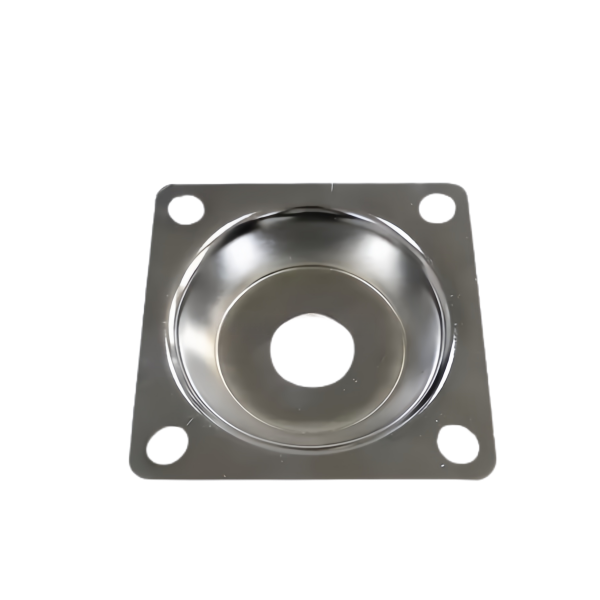
| Item | Stainless Steel Shallow Drawn Rectangular Tray |
|---|---|
| Brand | AUNOV |
| Designing | Design intent is read from the print, and any conflict in the drawing is raised before quoting. |
| Tooling | Die design and toolmaking stay in house, so die cost stays transparent, and maintenance is tracked against the part number. |
| Samples | Sample parts are measured and reported before submission, so the approved first article becomes the gauge reference, and later batches are gauged back to the signed sample. |
| Materials | Carbon steel (SPCC / DC01), 304 / 316 stainless steel, aluminium and brass are held on site; grade and temper are confirmed in writing before tooling. |
| Surface finish | Plating, powder coating, anodising or polishing, per the print; finish thickness and adhesion checked on the first article. |
| Processing | Die stamping with in-press forming and piercing; every stage is logged against your part number. |
| Equipment | Press shop with 5-250 T mechanical presses and dedicated dies; secondary ops run on CNC turning centres, inspection on the CMM. |
| Tolerance | +/-0.05 mm on bend positions, +/-0.1 mm on blank outline; critical dimensions carry CMM data with the shipment. |
| Delivery terms | FOB, with DDP offered for EU and US addresses, payment by T/T or L/C, quoted in USD or EUR; repeat orders reuse the approved first article. |
Related Products


Request a Quote for This Part
Send a drawing or sketch — get material advice, tooling cost and a per-piece price within 24 hours (working days).