
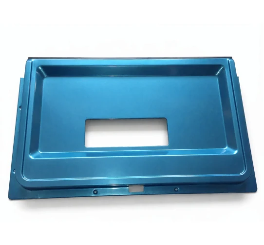
Hydroforming takes a tube and a closed die and uses fluid pressure to push the tube into the shape of the die. It sounds like a novelty alternative to stamping, and for a simple prismatic box it is one. What makes it interesting is what it does to the wall thickness, and what that means for a cover that has to be stiff, light and dimensionally stable.
The process is capable of shapes that cannot be stamped at all. That capability creates a design temptation — if hydroforming can make it, why not ask for it — and the answer involves the same three things every time: the pressure, the lubrication between the tube and the die, and where the material chooses not to go.
Pressure is a forming force, and it is limited by the die, not by the press
A hydroform has no punch. The tube is expanded outward against the die by internal pressure, and the pressure has to be high enough to bring the tube into contact with the die along its whole length — which means the pressure must exceed the yield strength of the material at the operating temperature, plus the friction losses along the path.
The consequences are structural rather than financial, but they determine the tooling envelope:
- The die must be pressure-tight and it must resist the hoop stress. A hydroform die is a pressure vessel as much as a forming die, and the split line has to be designed to contain that load without marking the part.
- The pressure rating caps the design. A geometry requiring 3000 bar needs a die and a intensifier system rated for it, and the safety case around that is not trivial.
- There is no adjustable draw-in. In a stamp the blankholder controls material feed. In a hydroform the only control is the pressure ramp, which is coarser. This is why a hydroformed part cannot absorb dimensional variation the way a stamped one can.
Thickness distribution is the central fact
Wherever the tube contacts the die, the die does the work and the tube is stretched two-dimensionally. Where the tube is not in contact, it can retain its original wall. So the thickness map follows the geometry exactly:
- Tight corners reduce in wall. A radius in the die forces the tube to stretch around it, and the wall thins. A small internal radius is the single most damaging feature on a hydroformed cover.
- Flat faces thin only where the tube contacts. A face that is planar does not require stretch, so the wall stays closer to nominal — but the perimeter of that face, where it turns to the radius, thins.
- Draw marks and unsupported sections do not thin. Where the tube spans a gap in the die, it stays at its starting thickness, and the transition into a supported region is where a sudden thickness change occurs.
- The corners of a square cover are always thin. Every rectangular hydroformed cover has four thin corners. This is not a defect, it is the process.
A drawing for a hydroformed part should therefore specify the wall as a map rather than as one figure. A nominal with a single tolerance band cannot be met, because the achievable variation across one part is several times the variation from part to part.
Aluminium grades differ enormously in how they hydroform
The alloy choice changes the process more than it changes the part.
- 1050 and 3003. The softest and most formable, and the usual choice for the deepest shapes. They hydroform easily and take a good surface finish. Lower strength, which is why they are rarely used where the part carries load.
- 5052. The standard structural sheet alloy. Forms well, has better corrosion resistance than the 3000 series, and is widely available in sheet. A good general choice for a cover that needs some stiffness.
- 6061. Strong and heat-treatable, but it forms considerably harder than the 5000 series and, critically, it is prone to the springback that comes with its lower ductility. A 6061 hydroform will need a sizing operation after forming.
- 5xxx versus 6xxx. The 5xxx series cannot be heat treated to high strength, so it is chosen for formability and corrosion behaviour. The 6xxx can be heat treated after forming, which raises strength but is only worth doing if the part needs it and if the forming is done in the O or T4 condition.
The temper is as important as the alloy. A T6 or T8 temper is much harder to hydroform and will crack in the tight radii. If the design calls for a hard temper, the forming has to be done soft and heat treated afterwards, and the part must be designed with the distortion that heat treatment introduces.
Surface: the die decides the finish, and so does the lubrication
The finish on the inside of the part comes from the tube’s original surface, drawn through the die. The finish on the outside comes from the die surface. This asymmetry has consequences for which surface should be decorated.
Where the part is to be polished or coated on the visible face, the visible face should be the die-contact face — because that is the one whose finish is controlled by a machined surface. Where the part is to be left natural on both faces, the inner surface quality is whatever the tube mill supplied.
Lubrication is more critical here than in stamping. The tube slides along the die over a much greater relative distance than a blank does, and lubrication is the only thing separating the tube from galling and from the surface tearing that hydroforming is prone to. Practical points:
- Lubricant selection must match the pressure. A conventional lubricant can be squeezed out of the contact zone at high internal pressure, and the failure appears exactly where the pressure is highest.
- The lubricant must be compatible with the aluminium, and it must not leave a residue that interferes with subsequent coating or bonding.
- Ventilation matters. The trapped air between tube and die has to be evacuated, because it prevents contact in the last few percent of the shape and leaves a region at starting wall thickness in the middle of a face.
Springback and sizing
Aluminium springs back, and a hydroformed part springs back more than a stamped one because there is no plastic strain imposed by a punch to hold the shape — the shape is held only by the die and by whatever residual stress remains.
The practical consequence is that a hydroformed part frequently needs a sizing pass: forming slightly oversize, then pressing the part to shape in a closed tool. This is often done in the same operation by venting the fluid and applying a mechanical closing force, and it is what gives the part its final dimensional accuracy and its good surface.
On a drawing this shows up as a tolerance question. A hydroformed part with a plus or minus 0.1mm general tolerance and no sizing step is not a realistic specification. Either the tolerance is relaxed to something achievable in forming alone, or the sizing step is written into the process and the tooling is quoted for it.
When a cover should not be hydroformed
Hydroforming is the wrong process in several identifiable situations, and recognising them on the drawing is cheaper than finding out on the press.
- Sharp internal corners. Below about one wall thickness of radius, the tube will not conform and the corner will be either unformed or cracked. Corners below that radius should be machined afterwards or the geometry should change.
- Very long thin-walled shapes. A long thin wall supported at intervals is prone to instability and to variable contact, and its thickness will be highly variable.
- Deep shapes with a small opening. As depth increases relative to diameter, the pressure needed to reach the last part of the shape rises steeply.
- High-volume flat panels. A stamped cover with a simple contour will be far cheaper at volume than a hydroform, and flatter.
- Parts needing a consistent wall for a functional reason. Where the wall thickness carries a pressure or a seal, a process whose output thickness varies across the part is not usable.
The last point is the important one. Hydroforming trades cost and tooling complexity for shape capability and part count. Where the wall thickness is the functional requirement, that trade is not available.
Questions worth asking on a hydroformed cover drawing
- Is the wall thickness specified as a map with a minimum, rather than as a nominal with a single band?
- Are the internal corner radii dimensioned, and are they at least one wall thickness?
- Which alloy and temper is specified for the forming condition, and is any heat treatment after forming noted with its distortion allowance?
- Is there a sizing step, and if so is the general tolerance achievable only after it?
- Which surface is the visible one, and is it the die-contact face?
- Is internal pressure specified as a process requirement, and is the vent point for trapped air identified?
- Is the lubricant specified as compatible with the alloy and with the subsequent coating?
- Are there features that must be machined after forming, and is the stock allowed for them present in the preform?
The last question connects this process to the previous page. A hydroformed cover that needs a flat mounting face or a threaded insert is a compound part, and the forming tolerance and the machining tolerance have to be budgeted together rather than separately.
If you are comparing this part with a machined or welded alternative, the guide to deep drawn covers lays out where drawing wins, where it loses, and what it costs either way.
Where this part is used
A hydroformed cover uses fluid pressure instead of a punch to form the panel, which means the shape follows the pressure path rather than a tool profile. That is the attraction – a smooth, variable-section cover with no draw beads and no local thinning, in a part where a conventional pressing would have to be split into several operations and welded. You will find hydroformed covers in instrument housings, in protective shrouds, in automotive covers and in the closures of pressure-containing assemblies.
The method has limits that are worth understanding before the drawing is committed. Because the pressure has to be sealed, the blank has to be stretchable enough to form without tearing and stable enough to hold a seal. Because the pressure does the forming, the die decides the finish and the lubrication decides the surface. And because a hydroformed part has no controlled material flow through a punch, the thickness distribution has to be predicted before the tooling rather than discovered afterwards.
What we need to quote it
Send the cover’s overall dimensions, the material grade and temper, and the stock thickness – and tell us whether the part is cosmetic or structural, because that decides how tightly the thickness distribution has to be controlled. Give us the required surface finish and whether any area must be masked. If the part is pressure-retaining once formed, say so, because a hydroformed cover’s seam and flange need to be designed as a pressure boundary rather than as a cosmetic closure.
Specifications
| Item | Hydroformed Aluminum Cover |
|---|---|
| Brand | AUNOV |
| Designing | Quotation is built from the drawing: DFM notes come back with the price rather than after tooling. |
| Tooling | Dies, fixtures and gauges are made in our own toolroom, so the die charge appears as its own quotation line, and ownership is confirmed on the quotation. |
| Samples | Production does not start until the sample report has been signed off. |
| Materials | 1050 / 3003 / 5052 / 6061 aluminium, 0.5-3.0 mm stock – temper matched to the forming depth or machining route of this cover. |
| Surface finish | Plating, powder coating, anodising or polishing, per the print; finish thickness and adhesion checked on the first article. |
| Processing | Coil-fed stamping, deburred and finished to the print; in-process checks sit between stages, not only at the end. |
| Equipment | Mechanical presses 5-250 T, in-press forming and piercing, with CNC turning centres for secondary operations and CMM inspection. |
| Tolerance | +/-0.03 mm on pierced holes, +/-0.1 mm on formed sections; critical dimensions carry CMM data with the shipment. |
| Delivery terms | FOB Ningbo or Shanghai, payment by T/T or L/C, quoted in USD or EUR; sea or air freight is quoted to your door. |
Related Products


Request a Quote for This Part
Send a drawing or sketch — get material advice, tooling cost and a per-piece price within 24 hours (working days).