
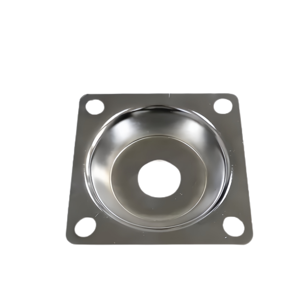
The Stainless Steel Deep Drawn Square Dish with Center Hole combines the part of a square draw that is genuinely difficult — the corners — with a feature that looks trivial and is not: a pierced hole in the middle of the formed bottom. The shell is produced in our toolroom’s draw dies on presses from 5 to 250 ton, in 304 and 316 austenitic sheet, and every engineering decision on this geometry funnels into two places: how much the corners thin as they flow into the die, and when in the sequence the center hole gets its edges. This page covers both, plus the grade choice and the blank work that makes a square dish producible at all.
Corner thinning on a square dish and how we budget for it
A square draw is really four corner draws connected by straight walls. The straight sections deform mostly by simple bending — they barely change thickness — while at each corner the material must flow inward and around, stretching over the die corner radius and thickening at the flange root where compressive stress piles up. The thinnest point lands at the punch corner radius, and on a square 304 dish we expect 10 to 18 percent thinning there from nominal wall, versus 3 to 5 percent along the straight walls. If the drawing specifies 1.0 mm nominal wall with a 0.85 mm minimum, that budget is already close to consumed by geometry alone, before any process variation gets a vote.
We budget explicitly at review. Punch corner radius is the strongest lever: holding at least 5 to 6 times material thickness, ideally 8 times, keeps the stretch at the corner spread over enough arc that thinning stays predictable. Blank holder force is the second lever — corners are where wrinkles form when the holder is too soft and where tears form when it is too hard, and the correct setting sits in a window we bracket on the first article rather than calculating once and hoping. The corner thickness on the first article is measured directly, by sectioning a sacrificial part or by ultrasonic point gauge on the four corners, and that measured value becomes the process’s reference for every lot that follows. A square dish whose corners measure 0.88 mm on first article will measure 0.86 to 0.90 in steady production; one that measures 0.84 is one hard batch of sheet away from scrap, and we say so before it becomes a delivery problem.
Blank development for a square draw starts with the corners
The blank for a square dish is not a square. The straight walls want their material from strips directly opposite them, while the corners want to pull from a quarter-round region, and a blank cut as a plain square forces the corner material to crowd and fold — the classic corner wrinkle that no blank holder force can fully suppress. The workable blank is a square with rounded or fully arced corners: the corner radius of the blank is developed from the corner depth, roughly a quarter-circle whose radius grows with the depth-to-corner-radius ratio of the part. We develop the shape on the first tool, cut trial blanks laser-cut at three candidate sizes, and tune to the trim line the part actually wants rather than the one the formula predicted — the formulas get the first guess within a millimeter or two, and the laser iterations close the rest.
Trim allowance is planned at the same time. A drawn square dish flange will not be uniform — the corners flow differently than the edges, and the flange width varies around the perimeter by a millimeter or more as-drawn — so the blank carries deliberate extra material, typically 2 to 4 mm of trim stock on edge, and the trim die cuts the final rim square and true. On this part family the trim happens in a second station with the part located on the drawn internal profile, so the trimmed rim is concentric to what the customer actually assembles against, not to an abstract blank center that stopped existing when the press came down.
Why the center hole is pierced after drawing, never before
The center hole in the bottom looks like it could go in the blanking die and save a station. It cannot. During the draw, the bottom of a square dish is not passive: material inside the punch profile flows outward toward the walls — the bottom surface stretches as the walls form, and any hole pierced in the blank before the draw deforms into an ellipse, growing along the flow direction and shifting toward whichever corner pulled hardest. A hole that starts 20 mm round in the blank can finish 22 × 18 mm and 1.5 mm off position, and no post-process fixes that on a formed part.
So the hole is pierced after forming, in the bottom of the drawn dish, flat on a bolster with the dish located on its trimmed rim or its internal profile. Pierced after drawing, the hole holds its roundness and its position to the formed geometry directly — typically +/-0.15 mm to the trim datum, comfortably inside what this family needs for a mounting or venting hole. The piercing punch rules also apply: hole diameter at least 5 times sheet thickness for a clean burnished shear with minimal burr, sharp hardened punch and die with clearance around 10 percent of thickness per side for austenitic stainless steel, and the burr direction specified — on this geometry we pierce from the outside face so the burr lands inside the dish where it does not sit against a mating surface.
Drawing 304 versus 316 in a shallow square shell
Both grades in this family are austenitic and both work-harden fast while forming — the draw force runs 30 to 40 percent above what mild steel of the same gauge would need, and the punch force curve keeps climbing as the shell forms rather than flattening out. The differences between them are real but narrower than the sales literature suggests. 316, with its higher nickel and molybdenum, draws marginally softer and tolerates the corner stretch a little more graciously; 304 is the cheaper default and forms this shallow square geometry without complaint when the corner radii are respected. Where the choice actually bites is in multi-stage work and in service: a dish destined for chloride exposure gets 316 without an argument, and a deeper draw version of this geometry that we develop in stages gets in-line annealing between draws regardless of grade, because work-hardened austenitic sheet will not survive a second draw unannealed.
One grade-specific caution we apply on 304: slow cooling through the sensitization range is avoided on any part that will see corrosive service, and the annealing practice on staged draws is specified accordingly. It costs nothing to schedule correctly and it is not recoverable afterward.
How we verify square dishes with a pierced center hole
Each lot of this geometry is checked against the failure modes the process actually risks:
- Corner wall thickness, measured at all four corners on sampled parts against the first-article reference — the budget discussed above, checked as-run, with the thinnest corner named in the report rather than averaged away.
- Hole geometry: diameter at two orientations across the hole to catch ovality, plus position to the rim datum, because a post-draw pierce that has drifted means the locating station is wearing.
- Trim quality on the rim: visual for edge condition, and sampled measurement of the trim line squareness to the drawn walls.
- Burr condition on the pierced hole, inspected from the specified burr side, since burr direction is a functional callout on this family.
- Wrinkle and score inspection on corner flange regions and draw-bead tracks, at the first-article-established blank holder settings, confirmed on the gauge readings of the run.
- Material certification per heat, and the draw process record — stations, anneal points, blank holder window — filed against the lot.
The verification list mirrors the process decisions on purpose: corners, blank, hole, grade, in that order, because that is the order in which this part can fail.
Parts like this one sit under the Custom Metal Stamping Parts range, whose overview page gathers the tooling logic, finishing options and tolerance notes shared across the family.
Specifications
| Item | Stainless Steel Deep Drawn Square Dish with Center Hole |
|---|---|
| Brand | AUNOV |
| Designing | Send the drawing, or a sample we can measure, the quotation comes back with a manufacturability review attached. |
| Tooling | Tooling designed and cut in house, held under your part number. |
| Samples | Approval samples ship with dimensional data and material certification. |
| Materials | Stock for this part leads with 304 / 316 stainless steel, alongside carbon steel (SPCC / DC01), aluminium, brass and copper, per the drawing. |
| Surface finish | Finish options: plating, e-coat, powder coating, anodising or passivation, as called out on your print. |
| Processing | Staged deep drawing with in-line annealing where needed, then pierced and machined in house. |
| Equipment | Mechanical presses 5-250 T, hydraulic presses 250-500 T, CNC turning and milling cells, a climate-controlled CMM room. |
| Tolerance | +/-0.1 mm on as-drawn features, +/-0.03 mm after machining. |
| Delivery terms | FOB standard, DDP offered for EU and US, T/T or L/C, D/P on repeat business, call-off scheduling supported. |
Related Products

Request a Quote for This Part
Send a drawing or sketch — get material advice, tooling cost and a per-piece price within 24 hours (working days).