
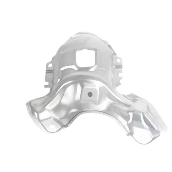
The Stainless Steel Deep Drawn Curved Cover Shell is the one geometry in our deep-drawn range that is neither round nor square: a cover shell with compound curvature, formed from 304 stainless steel, whose cross-section changes along its length and whose material has to flow in two directions at once to take the shape. The classic axisymmetric formulas that size round draws do not apply, the corner rules from box draws only half apply, and the process has to be developed per geometry. We form these shells in our toolroom’s draw dies with in-line annealing in the routing where the grades demand it, and this page covers what actually governs a curved stainless steel shell coming out of the press right.
Drawing a shell with compound curvature: neither round nor square
On a round draw, material flows inward from every direction at the same rate; on a box draw, the corners and edges have separate jobs but separable ones. A curved cover shell has neither luxury: the deep sections draw material from directions the shallow sections also want, the curvature makes the wall’s developed length vary continuously along the part, and the blank that feeds one end starves the other. The result is that blank development is done by iteration, not formula: we start from the developed surface, cut trial blanks laser-trimmed oversize, draw a shell, read where it tore and where it piled up, and revise. Two to four iterations is normal for this family, and the iterations are scheduled tooling work, not improvised scrap.
What the iterations converge toward is a blank with deliberate asymmetry — more material where the draw pulls hard, cut back where the material wrinkles from surplus — and a forming sequence that stages the curvature. A shell whose curvature sweeps more than a modest angle in one stroke concentrates its stretch at the transition zones; staged forming takes the curvature in two or three increments with intermediate anneals on 304, and each stage’s shape is designed to leave the next stage a fair, formable starting point. The stage shapes are engineering decisions we make and document, because a bad intermediate shape shows up only as a tear in the operation that inherits it.
Draw bead placement controls where the shell pulls from
On a curved shell, unrestricted blank holder force cannot do its usual job, because the required restraint differs around the perimeter — the zones feeding the deep curvature need to flow, the zones feeding the shallow sweeps need to be held back or they wrinkle. A uniform blank holder tight enough to stop the shallow-side wrinkles stops the deep-side flow dead, and the shell tears where it is deepest. The answer is draw beads: ribs and grooves cut into the die and holder faces that impose a controlled, repeatable resistance to material inflow, placed selectively so each perimeter zone is throttled to the rate its region needs.
We place beads from the tryout evidence, not from simulation alone. Forming simulation gives the first proposal — where the strain gradients concentrate, which boundaries need restraint — but the bead geometry that lands on the tool is tuned against drawn shells: bead height and shoulder radii adjusted until the material flows balanced, verified by circle-grid strain analysis on a tryout shell that tells us where the sheet actually stretched versus where the model said it would. On 304 the stakes are higher than on carbon steel because the material work-hardens as it fights the bead, and a bead set too aggressive hardens the inflowing edge until it splits at the punch radius a stage later. The bead settings that survive tryout are recorded as die data — height, radius, position per zone — so a die refurbish restores the developed geometry instead of resetting the development.
Kinking and tearing at the transition radii
Curved shells fail at their transitions — the radii where flat or gently curved regions sweep into tighter curvature — and they fail in two distinct modes that have opposite fixes. Kinking appears on the shallow side of a transition: the sheet, under compression as it conforms, buckles locally into a visible crease instead of stretching smoothly, and once a kink is drawn in, it is part of the shell forever. Tearing appears on the deep side: the sheet, stretched past its uniform elongation under the combined pull of curvature and blank holder, thins at a band and splits. The kink says the material is being pushed; the tear says it is being pulled too hard — and near a transition both happen at once, on opposite sides of the same radius.
The countermeasures are geometric before they are parametric. Transition radii on this family are held generous — six to ten times material thickness on 304 as the working floor — because a tighter radius multiplies the strain gradient across the transition and both failure modes at once. Where the design will not grant the radius, the stage sequence absorbs it: the shell takes the tight curvature in a late, well-annealed, well-lubricated stage with bead restraint locally relaxed at that zone. Blank holder and bead settings near transitions are always the last parameters locked, after the radii and staging are settled, because tuning pressure against a bad geometry produces a tool that only works on one coil of steel in five.
Springback on curved 304 shells and how the die is cut to fight it
Everything curved in sheet metal springs back, and 304 is worse than carbon steel at the same strength: high work-hardening means much of the forming stress is locked in as elastic strain that comes back out when the punch lifts. A curved cover shell shows it as shape change along its whole sweep — the curvature opens, the flange or rim planes twist relative to each other, and a shell that matched the gauge on the press is visibly off it in free state. On this family the change is not a fraction of a degree; free-state deviation of a millimeter or more across a long shell is ordinary, and the die is designed knowing it.
Compensation runs in layers. The punch and die surfaces are overcurved by the measured springback of the tryout shells, cut in the toolroom against the free-state shapes of real drawn parts rather than the nominal CAD, with the overcurve iterated until the free-state part lands on nominal. Where the shell’s own stiffness fights uniform compensation — a long curved shell can spring back non-uniformly along its length — the forming sequence distributes the curvature so no single stage imparts enough bend to spring asymmetrically. And where the application cannot tolerate residual-stress relaxation over time, a stress-relief anneal in the routing settles the shape at the temperature where the stresses let go, scheduled and priced as a real operation. What we do not do is chase springback with inspection: a shell measured off-nominal after forming is a process output, not a sorting problem.
How we verify curved cover shells against scan data
A shell with compound curvature cannot be honestly verified with calipers and a surface plate — the form is continuous, and the failures are local. Release verification on this family is scan-based:
- Structured-light or laser scan of sampled shells per lot, best-fit to the CAD in the drawing’s datum frame, with deviation reported as a color map plus named worst-point values at the transition zones the process history says are critical.
- Thickness verification at the scan-identified thinning zones — transitions and deep-curvature crowns — by ultrasonic point gauge or by sectioning the first article, against the drawing’s minimum wall and the first-article reference map.
- Strain verification on tryout and first-article shells by circle-grid analysis, confirming the formed strains sit inside the material’s forming-limit window with margin, and that the production shells match the strain distribution the tool was accepted on.
- Flange and rim geometry — flatness, hole or clip positions where the drawing carries them — measured on the free-state shell after the springback has fully expressed, at a settle interval the process sheet defines.
- Surface condition inspection for kink signatures, bead track marks and galling, since on a visible stainless steel shell the cosmetic and the functional failures share root causes.
- Anneal and process records per lot — stages, temperatures, bead settings as-run — filed with the material heat certification.
The scan report and the strain map from first article are archived as the part’s reference: every production lot is verified against the shape and strain signature the tool was proven with, which is the only comparison that detects drift before it detects scrap.
Drawing a cover like this is a chain of decisions — draw ratio, wall thinning, radii and trim. Our deep drawn covers design guide works through each of them with worked numbers.
Specifications
| Item | Stainless Steel Deep Drawn Curved Cover Shell |
|---|---|
| Brand | AUNOV |
| Designing | Share your print, or send a part to be measured, the quotation comes back with a manufacturability review attached. |
| Tooling | Every die designed and built in our toolroom, stored under your part number. |
| Samples | Approval samples ship with a full dimensional report and mill certificate. |
| Materials | 304 / 316 stainless steel leads the stock list for this part, alongside carbon steel (SPCC / DC01), aluminium, brass and copper, with grade selection confirmed at drawing review. |
| Surface finish | Plating, e-coat, powder coating, anodising or passivation as the drawing calls out, as called out on your print. |
| Processing | Staged deep drawing with in-line annealing where needed, pierced and finish-machined on the same floor. |
| Equipment | From 5 to 500 T of press capacity across mechanical and hydraulic lines; CNC turning and milling cells plus a climate-controlled CMM room. |
| Tolerance | +/-0.1 mm on as-drawn surfaces and +/-0.03 mm on machined surfaces. |
| Delivery terms | Prices FOB, with DDP for EU and US on request, T/T or L/C, with D/P for repeat business, call-off schedules and blanket orders supported. |
Related Products



Request a Quote for This Part
Send a drawing or sketch — get material advice, tooling cost and a per-piece price within 24 hours (working days).