
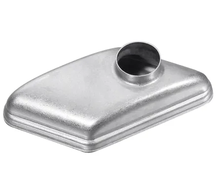
A stainless steel part that is drawn, then formed, then finished is three operations with three different tolerance philosophies, and the drawing has to reconcile them. The trouble is that each operation makes the part more accurate in some respects and less in others, and by the end the part is accurate in a place that does not matter and inaccurate in a place that does.
This page is about that reconciliation — how to decide which dimensions have to be formed, which can only be machined, and which are actually free.
Which dimensions are free, and why that is a design asset
On a drawn-and-formed part, some dimensions are determined by the tooling and are therefore stable; some are determined by the material’s springback and are variable; and some are consequences of other dimensions and are free to choose. Knowing which is which is most of the value engineering available on a part like this.
- Tooling-determined. Hole diameters and positions, cut-out profiles, the outer silhouette, boss diameters. These repeat essentially identically part to part as long as the tool is not worn, and they should carry the tightest tolerances on the part.
- Material-determined. Formed angles, flange lengths measured after bending, the height of a formed wall. These move with the material’s thickness and temper and cannot be held tighter than the incoming variation allows.
- Free consequences. The position of a formed feature relative to an as-drawn hole, once the drawing and the forming have both happened. This is the class of dimension that is usually mis-specified as tight when it is physically loose, or left unspecified and then found on the shop floor.
The productive question for a reviewer is: which class does this dimension belong to? A tight tolerance on a springback-driven dimension is not achievable. A loose one on a tooling-determined dimension is a missed opportunity, because that accuracy was already bought with the die.
Springback in stainless steel, and why the temper matters more than the geometry
Stainless Steel springs back more than mild steel because its yield-to-tensile ratio is higher, and the higher that ratio, the more of the elastic strain that was built into the part comes back when the load is released.
The temper condition multiplies this effect, and in a way that is easy to get wrong.
- Annealed. Low yield, high elongation. Forms easily with the least springback, but the part is soft and will deform in handling.
- Cold-worked (quarter hard, half hard, full hard). Higher yield, lower ductility. Springs back substantially more, and the harder the temper the worse the springback. On tight radii the harder tempers will crack.
- Post-form anneal. Forming in the annealed condition and annealing afterwards removes the residual stress that drives springback, giving a dimensionally stable part. On stainless steel this is often the only way to hold a formed feature accurately.
So the temper and the tolerance are the same decision. A formed angle specified to a tight band on a half-hard part is a specification that cannot be met. The same angle on an annealed-and-stress-relieved part can be held much tighter, because the elastic strain that causes the springback has been removed.
Work hardening limits how many forming operations a part can survive
Each forming operation hardens the material. A part that is drawn and then bent and then flanged is being formed three times, and by the third operation the material in the most heavily worked regions may no longer tolerate it.
This creates a practical ordering constraint.
- Do the largest deformation first. The draw is the biggest strain event and it should be first, on the softest material.
- Anneal between operations if the later ones are severe. Particularly where a tight bend follows a deep draw, because the drawn corner has already used up much of the available ductility.
- Avoid forming in the corner region. A bend or a flange that lands where the material was stretched in the draw is the most likely place for a crack, and there is no anneal available there without re-annealing the whole part.
This is why a drawing that specifies the final geometry without the process sequence often describes a part that cannot be made in that order. The reverse engineering — starting from the final shape and asking what order produces it — frequently shows that a small change to the design removes an entire operation.
Where the two operations disagree about the material
The draw leaves the part work-hardened and residual-stressed. The forming that follows works on that condition. Three specific problems follow.
- Forming accuracy is limited by the local condition, not the average. The corner from the draw is harder than the flange. A forming tool that closes on the whole part will bind on the corner and under-form the flange.
- Any machining after forming has to deal with stress relief movement. A machined flat will move after the part relaxes. On a part with a sealing face or a mounting face this is functional, not cosmetic.
- Distortion accumulates. The draw’s springback and the forming’s springback are both present at the end and they can be additive or offsetting depending on direction. Predicting the net flatness of a formed part is a matter of tracking both contributions.
The inspection plan has to account for this. Measuring a formed part immediately after forming and calling it out of tolerance is a common error, because the part has not finished relaxing. A defined settling period, or a thermal cycle, before final measurement makes the result repeatable.
Finish: the coating follows the geometry, not the reverse
On a formed part, the coating has to be applied after all forming is complete, which means the coating sees the formed geometry and has to accommodate everything about it.
- In a tight inside corner, a spray coating will not build the same thickness as on a flat. If the coating thickness is functional — for corrosion protection in a crevice, or for a dielectric requirement — the corner needs to be masked and coated separately, or the design needs a larger radius.
- On a hidden surface, coating is often unnecessary but is usually applied anyway. Masking the true hidden areas saves material and avoids the appearance of a thicker film.
- Where the coating will be a bearing or sealing surface, its thickness enters the tolerance chain. A 15 micron coating on a sealing face changes the assembled gap.
- Edges and sheared surfaces take coating differently from the flats and can look different on a visible part.
The useful specification here is not a general coating callout but a mask list: which surfaces are masked, which are deliberately coated thick, and which are acceptance-critical on thickness. A drawing that says “plate per print” without that list leaves the decision to whoever runs the plating line.
Tolerances that are actually achievable
Realistic bands for a formed stainless steel part, assuming stable tooling and a specified material band:
- Tooling-determined features: held to the machining tolerance the tool can hold, commonly plus or minus 0.02 to 0.05mm, and repeatable indefinitely.
- Formed angles: plus or minus half a degree to a degree, unless the part is stress-relieved or sized after forming.
- Overall dimensions affected by springback: budget the incoming thickness band into the tolerance, because it cannot be removed.
- Flatness on a part with a draw and a form: the largest tolerance on the part, and it should be measured after settling.
Stating these bands on the drawing does two things: it prevents the designer from specifying something unachievable, and it prevents the shop from being asked to hold a forming dimension to a machining tolerance. Both failures are expensive, and the second one shows up as a supplier quality dispute rather than as a clear engineering error.
Inspection staged to the process
- After the draw: wall thickness at the corner and at mid-wall, the flange position, flatness, and the corner condition on a sectioned sample.
- After forming: the formed angle and the formed length, measured in the formed condition and again after settling.
- After any machining: the machined features, referenced to the features that were already stable rather than to a formed surface.
- After coating: coating thickness on the critical surfaces, adhesion, and the masked areas confirmed clean.
- Final: functional dimensions only — the ones that determine whether the part fits and whether it seals.
Questions worth asking on a formed stainless steel drawing
- Which dimensions are formed and which are cut or machined, and are the formed ones toleranced for springback?
- Is the temper condition stated, and is the forming done annealed with a post-form stress relief?
- Is there an anneal between the draw and any severe forming operation?
- Does any bend or flange land in the drawn corner region, and if so, has that been checked for cracking?
- Is the coating thickness specified on the surfaces where it is functional, and is there a mask list?
- Where the coating sits on a sealing or bearing face, is it included in the assembly tolerance?
- Is the inspection staged after each operation, so a defect is attributed correctly?
- Is flatness measured after a defined settling period rather than immediately after forming?
The last two are process discipline rather than engineering, and they are what separate a part that arrives within specification from a part that arrives within specification on the day it is measured and out of specification a week later when it has relaxed.
Parts like this one sit under the Custom Metal Stamping Parts range, whose overview page gathers the tooling logic, finishing options and tolerance notes shared across the family.
Specifications
| Item | Sheet metal forming deep drawn deep drawing stainless steel parts deep |
|---|---|
| Brand | AUNOV |
| Designing | Driven by your drawing or a physical sample – samples are reverse-measured into a controlled drawing; changes are priced before they are made. |
| Tooling | Dies, fixtures and gauges are made in our own toolroom, so die cost stays transparent, and the die remains dedicated to your part. |
| Samples | Samples are issued for approval before the run, so the part is proven before it is made in volume, and production starts only after your written sign-off. |
| Materials | Carbon steel, 304 / 316 stainless steel, aluminium and brass are all held in stock; special grades are sourced to the drawing when volumes justify. |
| Surface finish | Natural, plated or coated – the print decides, and the agreed finish is logged; alternatives quoted with the quotation, samples approved in writing. |
| Processing | Coil-fed stamping, deburred and finished to the print; in-process checks sit between stages, not only at the end. |
| Equipment | Press shop with 5-250 T mechanical presses and dedicated dies, backed by CNC turning centres and a climate-controlled inspection room. |
| Tolerance | +/-0.03 mm on pierced holes, +/-0.1 mm on formed sections; GD&T per drawing, PPAP-style reports on request. |
| Delivery terms | FOB, CIF or DDP per Incoterms 2020, T/T with deposit and L/C for larger runs; repeat orders reuse the approved first article. |
Related Products

Request a Quote for This Part
Send a drawing or sketch — get material advice, tooling cost and a per-piece price within 24 hours (working days).