
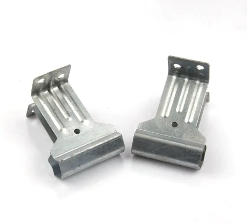
A multi-fin clip makes heat transfer its own problem
An aluminium stamped multi-fin clip bracket is a small part doing two jobs that pull against each other: it has to hold something mechanically, and it has to move heat. The fins exist for the second job – more surface area means more convective heat transfer – and the clip exists for the first. Almost every difficulty on this part comes from the fact that the same piece of aluminium is being asked to be a load path and a heat exchanger at the same time, in a part small enough that the two requirements are competing for the same millimetres.
We run these on 5-250 T presses with progressive and compound dies, coil-fed, deburred and finished to the print, with in-process checks between stages, secondary operations on CNC turning centres, and CMM inspection. Bend positions hold to +/-0.05 mm and the blank outline to +/-0.1 mm, with finer bands confirmed from capability data before quoting. Stock covers carbon steel in SPCC and DC01 grades, 304 and 316 stainless steel, aluminium and brass, with special grades sourced to the drawing when volumes justify. Your drawing sets the part, samples are reverse-measured into a controlled drawing, and revisions are re-quoted once rather than silently absorbed. This page is about the heat-transfer physics, the clip mechanics, and why the combination is harder than either alone.
What the fins are actually doing
A fin increases heat transfer by increasing surface area in contact with moving air. Two consequences define the design:
- Heat transfer improves with fin depth and with number of fins, but with diminishing returns. A fin’s effectiveness depends on how efficiently heat conducts along the fin and how much of its area is in moving air rather than in a stagnant layer. Past a certain fin depth, the tip of the fin is in air that has already been warmed by the rest of the fin and adds little.
- Fin spacing must exceed the boundary layer. This is the one that gets missed. If fins are too close together, the air between them moves slowly, warms up, and stops being able to carry heat away. A fin array with tight spacing can transfer less heat than a single plate with more area. Spacing has to be a specified dimension for the design to work, and it is as much a functional dimension as any hole position.
So the drawing needs to state fin thickness, fin depth, fin spacing and overall length as a set. Change any one of them and the part is a different thermal design, which is why these belong on a drawing as a functional group rather than as a general profile.
Aluminium, and why it is the right and demanding choice
Aluminium is the natural material here because its thermal conductivity is around twenty times that of stainless steel and several times that of mild steel. The cost of that choice shows up in three places:
- Formability. Aluminium is ductile and forms well, but it has a lower yield strength than steel, so a fin is easier to bend but also easier to deform permanently in handling, in assembly, or under a modest clamping force. On a part whose clip function depends on the fin’s springiness, an accidental bend is a scrapped part.
- Surface and oxide. Aluminium forms an oxide skin almost immediately, and that skin is what makes it look clean. But if drawing lubricant is trapped under it, that is a corrosion site, and a fin array traps lubricant and debris by its nature. This is why the cleaning step on a finned part is not optional.
- Anodising suits fins well, because it gives a hard, clean, thermally conductive surface that resists handling marks and does not need a coating thickness that would bridge the fin gaps. Where an uncoated part is specified, passivation is the sensible route.
Steel and stainless steel are held too, and where the clip’s structural duty dominates or where the environment is corrosive they can be the better choice – accepting the thermal penalty. This is a design decision worth making explicitly rather than defaulting to aluminium because fins suggest aluminium.
The clip side: spring behaviour in a small aluminium part
The clip’s job is retention, and retention is a force specification. Four things determine it:
- Section thickness. Retention force in a bending clip scales with thickness cubed, which makes the material’s thickness tolerance a force tolerance. This is the most common source of a clip that does not hold consistently across a batch.
- Material condition. Aluminium is more sensitive than steel here. A part formed from a slightly harder temper will be stiffer. Because temper affects both strength and springiness, it should be confirmed in writing rather than assumed.
- The fin’s effect on the clip. If the clip and the fins are one continuous piece, the fins add stiffness to the section the clip bends in – which increases retention force and reduces deflection, both of which change the design’s behaviour. Designing the clip so its bending section is separate from the finned area, and keeping the two considerations separate in the design, makes the part far more predictable.
- Wear at the contact point. On an aluminium clip, the contact point wears and work-hardens quickly, and it can gall or pick up material from the mating part. If the clip is intended to be removed and refitted many times, the contact area needs to be generous and the material choice should consider it.
Manufacturing: why a finned part is a forming challenge
A multi-fin geometry is not a simple progressive-die part, and the forming plan matters for reasons beyond cost:
- Fins are formed by fine pitch operations. A multi-fin array usually needs progressive piercing and forming operations at a fine pitch, and each one is a station in the die. On a part with a clip as well, the die has both the fine-pitch fin work and the clip forming in one sequence, which is a complex tool.
- The blank must be large enough to form the fins, and the material between the fins has to be there to begin with. A fin array consumes a surprising amount of blank, and the blank outline – at +/-0.1 mm – has to be controlled because the fin depths depend on accurate feed.
- Deburring a finned part is not trivial. A vibratory or belt finishing line that suits a flat bracket will not reach between fine fins. Deburring has to be done in a way that does not distort the fins, and it is a genuine process constraint worth discussing at review.
- In-process checks between stages are especially valuable here, because a fin tool that is wearing changes the fin’s height first and the clip’s geometry later. Catching it at the fin stage saves the whole batch.
Finishing, and the fin-gap problem
Zinc, nickel or chrome plating, anodising, passivation or e-coat are available, and the agreed finish travels with the part number. For a finned part the finishing requirement is unusual in one specific respect: any coating that thickens the fins reduces the fin spacing.
- Anodising is the best-behaved of the coating options here, because the layer is thin and hard and does not bridge a reasonable fin gap.
- Electroplating adds more thickness per unit of protection and can bridge the narrowest fin gaps. Where plating is specified, either the fins need a minimum spacing stated as a requirement, or the plating thickness has to be limited.
- Powder coating on a finned part is a bad fit – the coating is thick, it will bridge gaps, and it insulates the part, which defeats the fins’ entire purpose.
- Passivation or a bare, cleaned surface suits many heat-transfer applications and adds nothing dimensionally.
Where a coating is required for corrosion or appearance on a non-functional area, the functional areas – the fins, the clip’s contact surface, any mounting surface – should be masked. That should be on the drawing, because it is an operation per part.
Confirm who owns the die, on the quotation, before the run
Tooling and die design stay in house, so the die charge appears as its own quotation line and ownership is confirmed on the quotation. Samples are issued for approval before the run, the approved first article becomes the gauge reference, and mass production is gated on that approval.
Seven things that make a multi-fin clip bracket right first time, in rough order of how often they change the design:
- Fin spacing as a stated minimum, with the reasoning that too-tight fins reduce heat transfer. This is the single most valuable thing to put on a multi-fin drawing.
- Which surfaces are the heat-transfer surfaces, so the finish specification does not accidentally coat them.
- The clip’s retention force or deflection, stated as a force rather than a dimension, and separately from the fin geometry.
- Material grade and temper confirmed, since temper changes the clip’s force as well as its strength.
- Where the part is clamped during assembly, so a clamping force does not deform a fin.
- Whether the part is removed and refitted, which decides how much contact-area wear to allow for.
- Which faces are masked, and whether dimensions apply before or after finishing.
And the design question worth asking before all that: does the clip need to be part of this part at all. A separate clip – a stamped spring clip, a moulded one, or a purchased part – would let the finned component be a pure heat-transfer part designed only for that function, and would remove the interaction between fin stiffness and clip force entirely. On a part where the two requirements are fighting for the same material, that split is often the right answer.
This part belongs to our Custom Metal Stamping Parts range. The custom metal stamping parts pages collect the process notes, common materials and inspection points behind every product in the family.
Specifications
| Item | Aluminum Stamped Multi-Fin Clip Brackets |
|---|---|
| Brand | AUNOV |
| Designing | Your drawing sets the part – samples are reverse-measured into a controlled drawing; revisions are re-quoted once rather than silently absorbed. |
| Tooling | Die design and toolmaking stay in house, so the die charge appears as its own quotation line, and ownership is confirmed on the quotation. |
| Samples | Samples are issued for approval before the run, so the approved first article becomes the gauge reference, and mass production is gated on that approval. |
| Materials | Stock covers carbon steel (SPCC / DC01), 304 / 316 stainless steel, aluminium and brass; special grades are sourced to the drawing when volumes justify. |
| Surface finish | Zinc, nickel or chrome plating, anodising, passivation or e-coat; the agreed finish travels with the part number. |
| Processing | Coil-fed stamping, deburred and finished to the print; in-process checks sit between stages, not only at the end. |
| Equipment | 5-250 T presses running progressive and compound dies; secondary ops run on CNC turning centres, inspection on the CMM. |
| Tolerance | +/-0.05 mm on bend positions, +/-0.1 mm on blank outline; finer bands confirmed from capability data before quoting. |
| Delivery terms | CIF or DDP, with FOB available, payment by T/T, L/C at sight or D/P; each volume tier carries its own quoted price. |
Related Products


Request a Quote for This Part
Send a drawing or sketch — get material advice, tooling cost and a per-piece price within 24 hours (working days).