
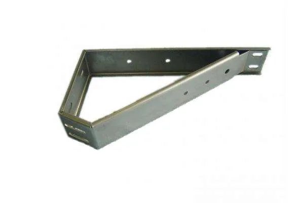
A motor bracket is a vibration problem wearing a fastener pattern
Mounting an electric motor looks like a hole-pattern question and is actually a vibration question. A motor is a mass on springs: its mass is supported by the mount’s stiffness, and if the natural frequency of that mass-and-mount system lands anywhere near the excitation frequency – which for a motor means the rotational frequency, its harmonics, or the blade-pass frequency of whatever it drives – the mount amplifies the disturbance instead of isolating it. The bracket’s holes, its stiffness and its fit to the motor’s feet are all part of that one calculation, and they interact in ways that a flat pattern drawing does not show.
We blank and progressively form these on automated lines with secondary tapping, bending and finishing, on 5-250 T presses running progressive and compound dies, with CNC turning centres for secondary operations and CMM inspection. Formed features hold to +/-0.05 mm and overall length to +/-0.1 mm, with CMM data on the critical dimensions shipped with the goods. This page is about the three things that decide whether a motor mount works: the location of the feet, the stiffness of the bracket, and what happens when they are not concentric.
Motor feet: the pattern is standard, the tolerance is not
Almost every motor a bracket is made for has its mounting feet at a defined pattern – IEC frame sizes and NEMA frame sizes each specify foot spacing, foot width, and the height of the shaft centreline above the mounting face. Those dimensions are fixed and are not where the difficulty lies. The difficulty is in the three things the standard does not fix:
- Flatness of the mounting face. Motors are not flat-footed in practice. Cast motor feet vary by a few tenths across the pattern, and a motor with one foot high will be twisted when it is tightened. A bracket that is flat does not fix this – it just means all the error now appears as bolt preload variation. The robust fix is a motor shim or a compliant mount, and it belongs in the assembly design rather than in the bracket, but the bracket’s flatness specification determines how much of the problem it can make worse.
- Foot position within its own casting. The nominal frame dimensions are nominal. Two motors of the same frame size from two suppliers can differ, and on a long-footed pattern the difference is significant.
- Foot hole size and shape. Cast holes are not precision holes. They are often elongated to allow adjustment, and they are cast at a position relative to a casting datum, not to the shaft centreline. This is why a motor bracket’s most important dimension is frequently not a hole at all.
Where the bracket also locates the motor rotationally – with a dowel, or with a hole that registers into a foot slot – that feature, not the bolt holes, is what sets the motor’s position. Getting the bolt pattern to fit is easy. Getting the motor centred on its shaft is a different tolerance requirement.
Stiffness: the reason to use a stamped bracket at all
Steel motor brackets are stamped because a stamped bracket is stiff for its mass and cheap in volume. The stiffness that matters is the bracket’s stiffness at the motor feet – and it is dominated by how the load gets from the feet into whatever the bracket is bolted to.
- Direct mount. The bracket is shallow and the feet sit almost directly above the base. Highest stiffness, lowest resonance frequency, most torque reaction capability. This is the right answer for a motor that must resist starting torque.
- Height or offset mount. The bracket lifts the motor, or offsets it to clear something. The load path now runs through a bending section, and stiffness falls roughly with the cube of the height. Doubling the bracket height can cost a factor of eight in lateral stiffness.
- Rail or channel mount. The motor slides on a profile and is located by the rail, with the bracket holding it down. Very stiff longitudinally, adjustable in position, and the slot means the location is set by the assembly rather than by the bracket.
Two consequences for the drawing. First, a tall bracket needs to be treated as a beam: its section depth and its wall thickness are structural variables, not just manufacturing ones. Second, resonance: a tall bracket lowers the natural frequency, and lowering the natural frequency moves it closer to the excitation frequencies. A bracket that is more comfortable to install can be a noisier installation. Where noise matters, the fix is usually a material or thickness change or a stiffening bead rather than a taller bracket.
Torque reaction, and the fastener that takes it
An electric motor produces torque in both directions. The reaction torque has to go into the mount, and this is the requirement that catches people out because it is easy to design a bracket that is perfectly stiff vertically and has no path for torque at all. Where the torque goes depends entirely on how the bracket is fixed:
- Bolted down to a rigid base. The torque is reacted by friction at the base joint, so the base joint needs real preload and the bracket needs enough area under the motor feet to resist the moment without crushing. The critical dimension is the footprint, not the hole pattern.
- Bolted through with clearance holes only. The bolts then act as dowels, and the bracket has to take the full moment in shear at the base. This is a much less forgiving arrangement and usually needs a second mounting point above the base or a flange joint.
- Through-bolted or clamped. A clamp joint reacts torque by bearing on the bracket’s flange rather than by friction, which is far more reliable and independent of the assembly’s torque discipline.
On a stamped bracket the reaction is usually handled by a flange or a foot that is wide enough to bear against the base, and by making the bracket tall enough that the moment is reacted over a real lever arm. Adding material at the foot is nearly always more effective than adding fasteners.
Resonance, and why the same bracket can be quiet or loud
With the excitation frequencies known – motor rotational frequency, pole-passing frequency, and the driven machine’s own frequencies – the mount can be designed rather than guessed at. The three useful rules without a full calculation:
- Keep the natural frequency away from the harmonics, not merely above them. A mount designed so that the first mode sits above the running speed will pass through resonance twice during every run-up and run-down, and those transients are usually louder than the steady state. A mount that is clearly below is usually quieter in practice than one just above.
- Aim for a low stiffness with a high damping mount if vibration isolation is the goal. Isolation and restraint are opposite requirements, and a rigid bracket that holds the motor firmly will transmit vibration while a soft one may let it walk. Most applications want restraint plus isolation of the transmitted force, which usually means elastomer between the motor feet and the bracket, not a soft bracket.
- Add stiffness where resonance is worst, not uniformly. A local stiffening bead at a foot changes the mode shapes and can move a resonance out of the band without changing the bracket’s overall function. This is a cheap, targeted fix.
Brackets for motor-driven equipment also need to survive the environment the motor sits in. Carbon steel is the default and takes plating or coating. 304 and 316 stainless steel are used where the bracket is in a wet or corrosive area, with the galling caveat at the threads. Aluminium is chosen where mass matters – and on a motor mount, mass is often the point, because a motor being moved by hand during installation is a real ergonomic concern. Brass and copper appear where conductivity or a specific corrosion requirement drives the design.
Drawing and review notes
Finish is selected from the drawing – plating, coating, anodising or passivation – with masking and laser marking available where needed, and masking is worth specifying for any datum or seating face because a coating there changes the dimension and the flatness. Quotation follows the print, not a catalogue: unusual walls, threads or tolerances are feasibility-checked first, and the agreed version governs every later batch. Tooling is built and held under your part number, so tooling lead time stays under our control and the charge is refundable against agreed volumes.
The questions that most improve a motor bracket drawing:
- What motor frame and whose motor? The frame fixes the pattern; the supplier fixes the real tolerance and the foot flatness.
- How is starting and reversing torque reacted – friction at the base, a clamp, or through-bolts?
- What is the bracket mounting to, and is that surface flat and stiff? A bracket designed for a stiff base does not work on a sheet-metal panel.
- What are the excitation frequencies, and is noise or vibration a complaint the part has to solve?
- Does the motor need to locate rotationally as well as bolt down?
Send drawings in PDF, DWG, STEP or IGS, or send a sample to be measured. First articles are checked on the CMM and critical dimensions carry CMM data with the shipment, which on a motor bracket means reporting the foot pattern relative to the mounting face and the foot positions relative to the shaft centreline – the two numbers that determine whether the part fits and whether the motor runs true.
This part belongs to our Custom Metal Stamping Parts range. The custom metal stamping parts pages collect the process notes, common materials and inspection points behind every product in the family.
Where this part is used
A motor mount bracket is usually drawn as a hole pattern and usually behaves as a vibration problem. A motor is a mass on springs: its mass is supported by the mount’s stiffness, and if the natural frequency of that mass-and-mount system lands near the excitation frequency – the rotational frequency, its harmonics, or the blade-pass frequency of whatever it drives – the mount amplifies the disturbance instead of isolating it. The holes, the stiffness and the fit to the motor’s feet all feed one calculation.
You will find these brackets on conveyor drives, on pumps, on fans, on machine tools and on the drives that run industrial equipment. The complaints arrive as noise, as a motor that has loosened its feet, or as a coupling that has needed realigning – and the root cause is usually stiffness and flatness rather than a hole in the wrong place.
What we need to quote it
Send the motor frame size or the foot pattern, the bracket material and thickness, and the motor’s mass and speed range if you have them – the resonance calculation needs both. Tell us how the motor is mounted: four bolts, slotted holes for adjustment, or a fixed pattern, because slotted holes change the stiffness and the frequency completely. If the bracket has held a motor before, a sample with a thickness measurement is worth sending alongside the drawing.
Specifications
| Item | Stamped Motor Mount Bracket |
|---|---|
| Brand | AUNOV |
| Designing | Quotation follows the print, not a catalogue – unusual walls, threads or tolerances are feasibility-checked first; the agreed version governs every later batch. |
| Tooling | Tooling is built and held under your part number, so tooling lead time stays under our control, and the charge is refundable against agreed volumes. |
| Samples | Pre-production samples come with a full inspection report, so the part is proven before it is made in volume, and production starts only after your written sign-off. |
| Materials | Carbon steel (SPCC / DC01), 304 / 316 stainless steel, aluminium, brass and copper – the grade is matched to the duty of this bracket. |
| Surface finish | Finish per the drawing: plating, coating, anodising or passivation, plus masking and laser marking where needed. |
| Processing | Blanking and progressive forming on automated lines, then secondary tapping, bending and finishing. |
| Equipment | 5-250 T presses running progressive and compound dies, with CNC turning centres for secondary operations and CMM inspection. |
| Tolerance | +/-0.05 mm on formed features, +/-0.1 mm on overall length; critical dimensions carry CMM data with the shipment. |
| Delivery terms | CIF or DDP, with FOB available, payment by T/T or L/C, quoted in USD or EUR; each volume tier carries its own quoted price. |
Related Products


Request a Quote for This Part
Send a drawing or sketch — get material advice, tooling cost and a per-piece price within 24 hours (working days).