
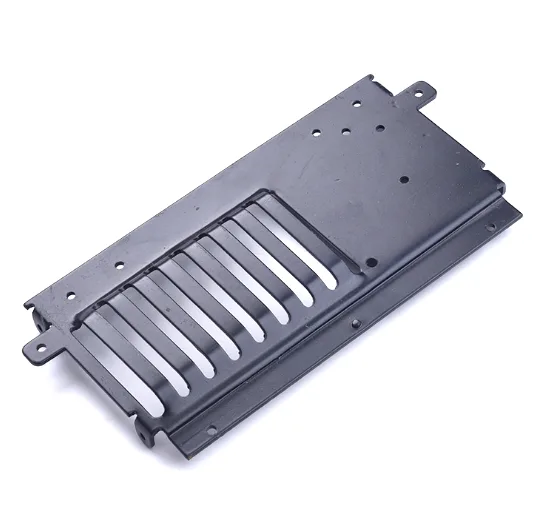
Hydroforming is now common enough that it gets specified by name, and naming the process is often the beginning of the problem rather than the solution. “Hydroformed” tells the supplier how the shape will be made. It says nothing about whether the shape is one hydroforming can actually produce, and it invites a design that ignores the two constraints that actually govern the process — internal radius and wall variation.
A part described as sheet metal fabrication, deep drawing and hydroforming is often a part where the designer wanted features from more than one process and did not check whether they can coexist in a single pressure-formed part.
What hydroforming will not do
The limits are structural and they do not move with a better die.
- Internal radii below about one wall thickness. The sheet cannot conform to a radius tighter than roughly its own thickness without either not forming or cracking. If a design calls for a sharp internal corner, the corner cannot be hydroformed and must be machined, radiused in a secondary operation, or redesigned.
- Sharp external corners with a small radius on a thin wall. These are achievable but they thin severely and they are where the part cracks first.
- Undercuts. The die has to release. A geometry that locks the die cannot be ejected without damaging the part, so any undercut must be either machined afterwards or formed in a separate operation before or after hydroforming.
- Thin walls spanning unsupported distances. A long thin section with a free span is unstable, forms unevenly, and its thickness varies far more than a supported region.
- Deep shapes with a narrow opening. The pressure needed to reach the last part of the geometry rises steeply as depth increases relative to the entry dimension.
Any one of these on a drawing converts the part from a single-operation part into a multi-operation part, and the quotation and the tooling cost change accordingly. Discovering this after the die is cut is expensive.
Combining hydroforming with other processes
Most real parts labelled hydroforming are not pure hydroforms. They are combinations, and the combination has to be planned rather than hoped for.
- Deep draw then hydroform. A preform is first drawn — typically a shallow cup — then hydroformed into the final contour. This is the standard route for shapes that need more depth than a preform tube can give. The preform’s wall distribution carries through, so the preform step is actually setting the thickness map.
- Hydroform then machine. Faces, holes, threads and sealing surfaces machined after forming. The forming tolerance then carries into every machined feature, which is why a fluid-formed part needs a defined datum strategy.
- Hydroform with pre-inserted features. A boss, pad or frame placed on the preform before forming, so the die shapes around it. The features end up accurately located because the die located them.
- Stamping features into the preform before hydroforming. Piercings, flanges and stiffening beads added in a separate stamping operation first. This is a very effective way to add features hydroforming cannot make.
The last one deserves more attention than it gets. A lot of features that look impossible in a hydroformed part — a flange for bolting, a stiffening rib, a mounting tab — are straightforward stamping operations on the flat preform, and adding them before forming costs one extra press operation instead of a whole second machining setup.
Wall thickness has to be specified as a map
This is the single most important thing about hydroforming and it is the thing most often left as a nominal. The wall thickness varies across a single part by a large multiple of the part-to-part variation, and the variation follows a predictable pattern.
- Where the sheet contacts the die, it stretches two-dimensionally and thins. The more the contour curves away from a straight line, the more it thins.
- Internal corners are the thinnest points. Every rectangular hydroformed part has four thin corners and this is inherent to the process.
- Flats are close to nominal, with the thinning concentrated at the perimeter where the flat turns into a radius.
- Unsupported spans retain their starting thickness, and the transition into a supported region is where a sudden change occurs. This shows up as a visible ridge or a thin band and it is a functional concern where the part has to take a load.
A workable specification therefore has three numbers rather than one: a minimum wall that applies everywhere, a nominal or band for the flat regions, and a maximum difference between supported and unsupported regions where that matters. Where the part carries pressure, the minimum is the design wall and it is set by the corners, not by the nominal.
Springback and the sizing question
A hydroformed part is not held in shape by anything except the die and its own residual stress, so it springs back more than a stamped one. Where a dimensional tolerance is tighter than forming can hold, a sizing step is required: forming slightly oversize, then closing the part in a tool to bring it to size.
Several options exist and they differ in what they cost and what they achieve.
- Coining in the same die by venting the fluid and applying a mechanical closing force. The usual answer, and it also improves the surface.
- A separate sizing tool. More tooling, more cycle time, better control.
- Restrict the tolerance to what forming alone achieves. Often the correct commercial answer at moderate volumes.
The choice has to be made on the drawing, because “plus or minus 0.1mm” on a hydroformed cover is either a realistic specification with a sizing step or an unrealistic one without it, and neither the designer nor the supplier can tell which was meant.
Lubrication and venting are process requirements, not shop details
Two things about hydroforming routinely cause rejects and neither is visible on the part drawing.
Lubricant choice is pressure-dependent. The lubricant is subjected to the full internal pressure over the contact area, and a conventional lubricant can be squeezed out of the contact zone. The failure appears exactly where the pressure is highest — usually the deepest part of the form — as galling, surface tearing or a torn corner. High-pressure lubricants exist for this reason.
Trapped air prevents final contact. The air between the sheet and the die has to be evacuated, and where it is not, a region of the part retains its starting thickness and its starting shape. This shows up as an incompletely formed area in the middle of a face, and it looks like a tool defect rather than a venting defect.
On a specification these belong as process notes: the lubricant class required, and the vent location or the requirement that the preform be vented. Both are cheap to state and expensive to diagnose from photographs of bad parts.
Materials and temper
The alloy selection for a hydroform is dominated by formability, which pushes hard against the other requirements.
- 1050 and 3003 form most easily and give the best finish, at the cost of strength. Deep shapes normally use these.
- 5052 is the standard structural choice — good formability, good corrosion behaviour, widely available in sheet.
- 6061 is strong and heat treatable but forms much harder and springs back more. It is used where post-forming heat treatment is worth the distortion it causes.
- Temper matters as much as alloy. A T6 or T8 temper will crack in a tight radius. If the design needs a hard temper, the part is formed soft and heat treated afterwards.
- Stainless Steel can be hydroformed but needs higher pressure, a more aggressive lubricant and closer radius control, and it will gall if the lubrication is wrong.
Where a part is formed in the soft condition and heat treated afterwards, the distortion allowance has to be in the design. Aluminium will move measurably in a solution-and-age cycle, and on a part with a sealing face or a flat mounting face that movement is functional.
Inspection that reflects how the part was made
- Wall thickness map, measured at the corners, at mid-flat, and at any unsupported region — not a single wall check.
- Corner radius conformity. A corner that did not fully conform is under-thinned and often cracked on the inside of the bend.
- Forming completeness, particularly in the last portion of the shape, which is where insufficient pressure and trapped air show up.
- Surface condition on the die-contact face, for galling and for lubricant residue.
- Flatness or contour measured after any sizing step, by a stated method.
- For combined parts, the features added by the secondary processes measured against the forming’s contribution to their position.
Questions worth asking on a hydroformed part drawing
- Are all internal radii at least one wall thickness, and if not, which ones are machined or radiused afterwards?
- Are there any undercuts, and how is each one produced — machined, or formed before hydroforming?
- Is the wall thickness given as a map with a minimum, a flat-region band, and a limit on unsupported regions?
- Is there a sizing step, and is the general tolerance achievable only after it?
- Is the preform route specified — drawn preform or tube — since that sets the thickness map?
- Is the lubricant class and the venting requirement stated as process requirements?
- For features added by other processes, is the operation and its order stated, and is the feature position toleranced against the forming variation?
- For a heat-treated part, is a distortion allowance included in the flatness or contour tolerance?
The question about operation order is the one that most often gets answered differently by the designer and the shop. “Hydroformed with machined mounting holes” does not say whether the holes are machined before or after forming, and the two produce different parts at different costs with different tolerances.
This part belongs to our Custom Metal Stamping Parts range. The custom metal stamping parts pages collect the process notes, common materials and inspection points behind every product in the family.
Specifications
| Item | Sheet Metal Fabrication Sheet Metal Deep Drawing Parts Hydroforming |
|---|---|
| Brand | AUNOV |
| Designing | Send drawings, or send a sample to be measured – DFM notes are returned before any tooling is cut; revisions are re-quoted once rather than silently absorbed. |
| Tooling | Our toolroom covers die design, wire-cut EDM and maintenance, so a die can be re-cut against the approved drawing, and ownership is confirmed on the quotation. |
| Samples | First-article samples ship with a dimensional report and material certificate, so any deviation is corrected at sample stage, and the signed sample is kept for future reorders. |
| Materials | Materials held include carbon steel, 304 / 316 stainless steel, aluminium and brass; mill certificates and heat numbers accompany the first article. |
| Surface finish | Zinc, nickel or chrome plating, anodising, passivation or e-coat; finish thickness and adhesion checked on the first article. |
| Processing | Coil-fed stamping, deburred and finished to the print; in-process checks sit between stages, not only at the end. |
| Equipment | Mechanical presses 5-250 T, in-press forming and piercing, with CNC turning centres for secondary operations and CMM inspection. |
| Tolerance | +/-0.05 mm to +/-0.1 mm across the part; finer bands confirmed from capability data before quoting. |
| Delivery terms | CIF or DDP, with FOB available, payment by T/T or L/C, quoted in USD or EUR; sea or air freight is quoted to your door. |
Related Products


Request a Quote for This Part
Send a drawing or sketch — get material advice, tooling cost and a per-piece price within 24 hours (working days).