
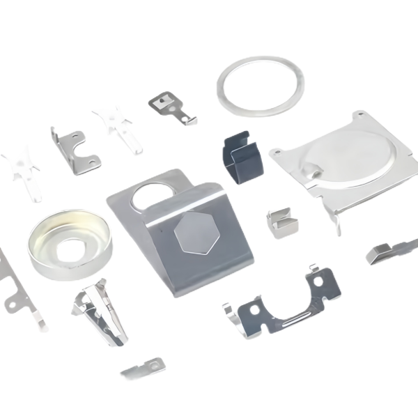
The Assorted Small Stamped Brackets Clips and Washers are the high-volume end of our press work: parts under roughly thirty millimeters in their largest dimension, blanked and formed in progressive dies on our mechanical presses from 5 to 250 ton, in carbon steel and stainless steel at gauges from 0.3 to 2.0 mm. Small parts concentrate different problems than large ones — a burr that would be irrelevant on a bracket is a functional feature on a 6 mm washer, and a springback of two degrees is half the part’s geometry on a small clip. This page covers the engineering that decides whether a bin of small stampings assembles or gets returned.
Progressive die design for parts under thirty millimeters
A progressive die carries a strip of material through a series of stations, each station adding features, with pilot holes in the strip’s carrier holding location from station to station. At small part sizes the arithmetic gets tight: pilots are small and strip lift forces are proportionally large, so pilot clearance, strip lifters and feed pitch interact at a scale where a 0.02 mm feed error is a visible mis-hit on a 8 mm part. We design the strip layout around part stability — carriers sized to the stock’s stiffness at gauge, pilots spaced for the longest strip, and idle stations inserted where the strip needs a straightening or a rest between heavy operations. The stations run in deliberate order: pierce the pilots first, blank the outline late, form after any blanking that would change the material’s local stiffness, and coin the critical geometry at a station where nothing downstream will disturb it.
Part-in-strip strength is the design constraint nobody sees until the scrap report. A 12 mm bracket attached to its carrier by two 1.5 mm-wide tabs survives stripping at production feed rates; the same part on one tab twists in the die and every station after the twist hits it off-center. We check carrier and tab proportions on the strip layout before steel is cut for the die, because the fix is free on paper and costs a die recut in metal.
Burr direction decides bracket orientation in the assembly
Blanking leaves a burr on the die side of the part — a sharp, rolled edge on the face that was down in the die. On small parts the burr is not cosmetic. A bracket that slides into a channel with its burr face leading wedges on the burr height; a washer clamped burr-side-down sits on a burr ridge instead of its own flat, and a 0.05 mm burr under a clamped washer is a straightness problem in the assembly. The die design sets burr direction the same way it sets every other feature: which face is down at blanking is chosen so the burr lands on the non-functional face, and the process sheet records it, because the assembly drawing’s orientation notes are only useful if the parts arrive with the burr where the design assumed.
Where the drawing calls for deburred parts we use vibratory finishing in bulk, which on small hardware is cheap and effective, but it changes edge geometry — the sharp blanked edge rounds slightly, and a press-fit feature sized on the blanked edge can lose its interference to the media. Parts with functional blanked edges get deburred selectively or get the burr managed by die maintenance instead: sharp punch and die, tight clearance maintained on a parts-per-sharpening count, so the burr height stays below the drawing’s allowance without touching the edge profile the fit depends on. Die sharpening is scheduled on measured burr height, not on calendar — the burr gauge reads every lot, and the sharpening happens when the reading says so.
Springback correction on small formed clips
A small clip is often nothing but a bend: a strip of formed metal whose whole function is the force it exerts at its free state. Springback on such parts is the product, in the wrong direction — the clip relaxes two or three degrees after forming on carbon steel at 0.5 to 1.0 mm, and the contact force it was drawn to deliver drops with it. At small sizes the correction has an advantage: the bend radii are small relative to the stock, and bending over a sharp radius with significant through-thickness strain shifts the mechanics toward coining, where the material is compressed at the bend line instead of merely bent and the springback drops sharply.
So small clips get coined bends where the geometry allows — bottomed punch to die with a deliberate Ironing of the bend zone, at tonnage the press schedule can hold — and the free-state angle holds within a degree or so across material lots. Where the clip is too delicate to coin, or the material too hard, the die overbends by the measured springback instead, angle compensation per bend per material hardness band, with the compensation values recorded in the die record from tryout parts. On clips whose contact force matters to the customer’s function, we go one step further and define the acceptance test functionally: the clip’s deflection force at a specified displacement, measured on a small force fixture, rather than an angle callout that the angle cannot guarantee. The functional test is cheaper to run than the angle is to hold, and it measures what the customer actually buys.
Washers blanked in the same press run: flatness and parallelism
Washers look like the simplest stamping in the assortment and are quietly the most demanding on flatness. A blanked washer carries the blanking operation’s stress distribution — the pierced hole’s roll-over zone pulls the surrounding material slightly into a dish, and the blanked OD leaves its own stress ring — and the two combine into a washer that is not flat to the tolerance a sealing or shimming application needs. Free-blanked washers at small sizes typically hold flatness around 0.05 to 0.1 mm on the blank side; where the drawing calls for tighter, the routing adds a shaving or coining station that sizes the washer between flat hardened faces, and the flatness drops below 0.02 mm.
Parallelism between the two faces is the same story at smaller magnitude — the dished stress state makes the faces slightly non-parallel until the coining station flattens it out. Hole-to-OD concentricity is the third washer dimension, and it is manufactured by tooling, not inspection: pierced hole and blanked OD in the same station on a common die center, with the washer located on the pierced hole by a hardened post when the OD blanking punch comes down. A washer punched that way runs concentric within 0.03 mm at small sizes and stays there for the die’s life; a washer blanked in one station and pierced in another inherits the strip’s feed error into its concentricity forever.
How we verify small stampings with first-off and attribute sampling
Small parts come in tens of thousands, so verification is structured around the first-off piece and a disciplined sampling plan rather than around measuring everything:
- First-off approval at setup: the strip’s first finished part measured fully — all functional dimensions, burr side and burr height, formed angles or clip free-state, washer flatness and concentricity — against the drawing and the die record, before the run is released to speed.
- In-run dimensional sampling on a defined frequency from the control plan: critical dimensions checked on drawn samples each interval, with results logged so drift in die wear shows as a trend line, not a surprise.
- Burr height gauge readings per sampling interval, feeding the die-sharpening schedule directly — the measurement that keeps the sharpening decision empirical.
- Attribute verification on the functions the parts exist for: clip deflection force on sampled parts from each lot on the force fixture, washer flatness on a surface plate with feeler or indicator per the drawing’s callout, bracket hole positions on a go/no-go location gauge built for the part number.
- Material certification per heat and coil, cross-referenced to the lot, with coil identity recorded at the feed so a question about one bag of washers traces to one coil of steel.
- Final visual sampling for cosmetic and edge condition per the drawing class, with inspection lighting specified so the standard is reproducible between inspectors.
The die record and the first-off piece are archived per part number, and every lot’s samples are compared back to that reference. On small stampings, the die wears gradually and the material varies by coil — the verification system is built to catch both slowly enough to act and precisely enough to trust.
Parts like this one sit under the Custom Metal Stamping Parts range, whose overview page gathers the tooling logic, finishing options and tolerance notes shared across the family.
Specifications
| Item | Assorted Small Stamped Brackets Clips and Washers |
|---|---|
| Brand | AUNOV |
| Designing | Share your print, or send a part to be measured, our engineers reply with a manufacturability assessment and pricing. |
| Tooling | Dies designed and built in our own toolroom, with your part number on the tool record. |
| Samples | Sample parts arrive with a full dimensional report and material certification. |
| Materials | Held stock: carbon steel (SPCC / DC01), 304 / 316 stainless steel, aluminium, brass and copper, per the drawing. |
| Surface finish | Surface treatment per the drawing: plating, e-coat, powder coating, anodising, passivation, selected against the drawing requirement. |
| Processing | Staged deep drawing, with in-line annealing where the draw ratio requires, then pierced and CNC-machined in house. |
| Equipment | Mechanical presses 5-250 T and hydraulic presses 250-500 T, CNC turning centres and a climate-controlled CMM room. |
| Tolerance | Drawn tolerances held to +/-0.1 mm, +/-0.03 mm on machined surfaces. |
| Delivery terms | FOB as standard, DDP available for EU and US destinations, payment T/T or L/C, D/P for repeat accounts, scheduled call-offs welcome. |
Related Products


Request a Quote for This Part
Send a drawing or sketch — get material advice, tooling cost and a per-piece price within 24 hours (working days).