
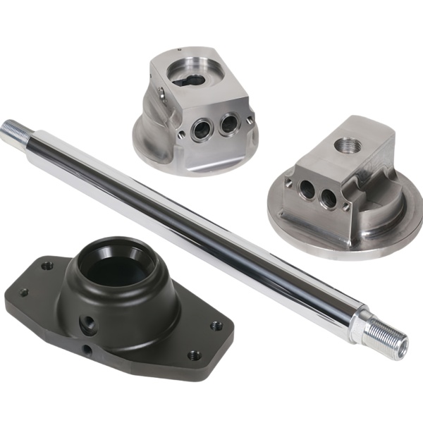
Shaft runout relative to the pump housing bore is the primary source of seal wear and leakage
In any rotating-shaft pump—gear pump, vane pump, centrifugal coolant pump—the mechanical seal or shaft packing rides on the shaft surface at the point where it exits the housing. If the shaft has 0.03 mm of total indicated runout at that location (measured relative to the housing bore axis), the seal lip is forced to track a wobble path that generates localized heating, accelerated wear, and eventually a leak path. The relationship between runout and seal life is not linear: doubling the runout from 0.02 mm to 0.04 mm typically reduces seal life by a factor of 3 to 5, because the seal lip’s ability to follow the shaft motion is exceeded and it begins to hydroplane intermittently.
We hold shaft runout at the seal land to 0.015 mm TIR maximum for pumps operating above 1800 rpm, and 0.025 mm for slower applications (< 800 rpm). The runout is measured after final grinding but before assembly, with the shaft supported on V-blocks at the bearing journals and a dial indicator at the seal land. Parts exceeding the limit are reground with a compensating offset—the amount of stock removal is typically 0.02–0.05 mm, well within the grind allowance that was designed into the blank from the start.
The fit between the shaft and the housing bore determines where the radial load is carried
A steel shaft running in a CNC-machined pump housing bore can be designed as a sliding fit (clearance), a press fit (interference), or a precision running fit with a bushing. Each choice carries different implications for load distribution, lubrication, and manufacturability. The most common mistake we see on customer drawings for small-to-medium pumps (shaft diameter 10–30 mm) is specifying a clearance fit without also specifying a minimum oil film thickness or a surface finish requirement for the bore.
A shaft-to-bore clearance of 0.015 mm on a 20 mm diameter shaft sounds reasonable until you calculate the Sommerfeld number at operating speed. At 3000 rpm with SAE 30 oil at 70 °C, that clearance produces a nominal film thickness of about 3 µm—which is thinner than the combined roughness of a ground shaft (Ra 0.4 µm → Rq ~0.5 µm) and a reamed bore (Ra 1.6 µm → Rq ~2 µm). The result is mixed lubrication (boundary + hydrodynamic) with intermittent metal-to-metal contact and a specific wear rate that may be acceptable for a 2000-hour service life but will not reach 10,000 hours. We push back on drawings like this by recommending either a tighter clearance (0.008–0.012 mm with hardened/ground bores) or a bronze bushing that provides a compatible running surface and can be replaced when worn.
Housing flatness at the mounting interface controls internal gear mesh alignment
For external gear pumps and gerotor pumps, the housing cover (the “back plate” or “wear plate”) must sit perfectly flush against the main body to maintain the designed side clearance between the gear faces and the housing. A flatness deviation of 0.02 mm across the sealing surface translates directly to a 0.02 mm variation in side clearance around the gear periphery. Since typical side clearance on these pumps is 0.015–0.040 mm, a 0.02 mm flatness error means one side of the gear is in metal-to-metal contact while the opposite side has double the designed clearance.
The immediate symptom is reduced volumetric efficiency (slip increases at the large-clearance side) and elevated temperature at the rubbing contact. The long-term symptom is scoring on the gear face and the housing surface, followed by catastrophic seizure if the pump runs dry even briefly. We machine both mating surfaces in the same setup whenever possible, holding each to 0.01 mm flatness over the full gasket area. When the cover is machined separately (because of geometry or machine-travel limits), we use a lapping operation that brings both surfaces to within 0.005 mm of optical flatness—a process that takes about 2 minutes per surface on a rotary lap with 5 µm abrasive slurry.
Port timing in the housing body affects pulsation more than the gear tooth profile does
The shape and position of the inlet and outlet ports in a gear pump housing determine the fluid dynamics of the pressure transition as each gear tooth passes from the low-pressure side to the high-pressure side. If the port edges are sharp and positioned such that two tooth spaces are simultaneously connected to both inlet and outlet during the transition (a condition known as “trapped volume”), the fluid in those spaces undergoes rapid compression and expansion that produces pressure spikes, noise, and cavitation erosion near the port boundaries.
Relieving this trapped-volume condition requires either pre-relief grooves (small channels that connect the trapped space to the inlet or outlet slightly before the main port opens) or asymmetric port timing that staggers the opening of successive tooth spaces. We model this using a lumped-parameter simulation that predicts pressure ripple amplitude as a function of port geometry, then cut the reliefs using a small-diameter ballnose end mill (2–3 mm) programmed to follow the calculated trajectory. The difference between a housing with optimized reliefs and one without is typically 3–6 dB in sound pressure level at the pump’s blade-pass frequency—a difference that is clearly audible and often determines whether the pump passes an OEM noise specification.
Material choice for the housing affects thermal growth mismatch with the cast iron or aluminum end bells
Pump housings are frequently assembled between end covers made of different materials—a cast iron bearing frame on one side and an aluminum adapter on the other, for example. When the pump operates at elevated temperatures (hot oil, ambient summer conditions, or proximity to an engine or motor), each component grows according to its coefficient of thermal expansion. Steel (12 µm/m·K), cast iron (11 µm/m·K), and aluminum (23 µm/m·K) all expand at different rates, and the housing sits in the middle carrying the resulting differential strain through its bolt pattern and its shaft seals.
On a pump with a 200 mm bolt circle and a 60 °C temperature rise from cold to operating condition, the differential growth between an aluminum end bell and a steel housing is approximately 0.13 mm. If the bolt holes have standard clearance (0.5–1.0 mm oversize), this growth is accommodated without issue. But if the design uses close-tolerance dowel pins for registration (common on OEM pumps where the housing must be removed and reinstalled during service), the pins bind unless they were designed with elliptical clearance in the axial direction or were made from a material with intermediate CTE (such as austenitic stainless steel at 16–17 µm/m·K). We review every pump drawing for this condition and flag it when we see pinned interfaces between materials whose CTE differs by more than 8 µm/m·K over a temperature swing exceeding 40 °C.
How we validate a new pump housing design before committing to production tooling
Before cutting production quantities of a new pump housing design, we build a prototype batch of 5–10 pieces from solid bar or billet (not from forgings or castings, which have longer lead times) and assemble them with production-grade gears, shafts, and seals. These prototypes go through a test sequence that includes:
- Geometric validation — full CMM inspection against the product drawing, with special attention to bore parallelism, port timing dimensions, and seal-bore roundness.
- Static pressure test — 1.5× maximum rated pressure for 10 minutes with no external leakage and no permanent deformation (re-measure critical dimensions after the test).
- Run-in cycle — 50 hours at rated speed and pressure with periodic efficiency measurements; oil samples taken at 10-hour intervals for particle count analysis.
- Thermal cycle — five cycles between –10 °C and +90 °C (oil temperature) with a pressure hold at each extreme; check for seal leakage and bolt torque retention after the sequence.
Only after passing all four stages do we approve the design for production tooling (dedicated fixtures, custom tooling for port reliefs, and optimized cycle times). This protocol adds roughly 3 weeks to the project schedule compared to jumping straight to production, but it has prevented three field failures in the past two years where the prototype testing revealed a port-timing resonance that did not show up in the customer’s own CAD-based flow simulation.
The CNC Machining Parts range is the parent for parts like this one; tooling logic, finishing options and tolerance notes for the whole family are gathered on its overview page.
Specifications
| Item | Steel Shaft with CNC Machined Pump Housings and Bases |
|---|---|
| Brand | AUNOV |
| Designing | Send us your 2D drawing, or mail a base sample for measurement, DFM feedback is returned with the quote. |
| Tooling | Dies designed and built in our own toolroom, with your part number on the tool record. |
| Samples | First articles go out with a full dimensional report and mill certificate. |
| Materials | Stock for this part leads with carbon steel (SPCC / DC01), alongside 304 / 316 stainless steel, aluminium, brass and copper, per the drawing. |
| Surface finish | Surface treatment per the drawing: plating, e-coat, powder coating, anodising, passivation, fixed at the drawing review. |
| Processing | Progressive deep draw stages with in-line annealing as the draw ratio demands, then pierced and CNC-machined in house. |
| Equipment | Mechanical presses 5-250 T, hydraulic presses 250-500 T, CNC turning and milling cells, a climate-controlled CMM room. |
| Tolerance | Drawn tolerances held to +/-0.1 mm, +/-0.03 mm after machining. |
| Delivery terms | Prices FOB, with DDP for EU and US on request, T/T or L/C, D/P on repeat business, blanket orders and call-offs supported. |
Related Products



Request a Quote for This Part
Send a drawing or sketch — get material advice, tooling cost and a per-piece price within 24 hours (working days).