
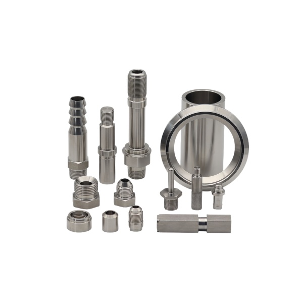
Coupling bore tolerance relative to the shaft determines the fit class—and the misalignment it can accommodate
A machined coupling that connects two shafts must fit both shafts with the intended clearance or interference while maintaining concentricity. The bore tolerance band directly controls which fit class is achieved: a bore machined to H7 (e.g., 25 +0.021/0 mm) on a shaft ground to h6 (25 -0.013/0 mm) produces a clearance fit with 0–34 µm of clearance—suitable for a sliding coupling that needs to be removed for maintenance. If the same bore is machined to H6 (+0.013/0), the maximum clearance drops to 24 µm, which reduces radial play but makes assembly more sensitive to shaft parallelism error.
The practical implication is that a coupling specified as “slip fit” on the drawing can behave as a “line-to-line fit” or even a light interference fit if the bore is machined to the low end of its tolerance and the shaft is at the high end. We target the midpoint of the bore tolerance band (not the nominal) as our process aim, giving us equal margin on both sides. For couplings that must accommodate angular misalignment (jaw couplings, bellows couplings, disc couplings), we hold the bore to H6 minimum and verify the actual clearance with an air gauge before shipping; any coupling with less than 5 µm of measured clearance is flagged for review because it may bind during installation if the shafts are not perfectly aligned.
Ring fitting cross-section affects how much clamp load reaches the seal without crushing the ring
A ring fitting—a circular clamp or retaining ring that holds a seal, a bearing, or a hose—transmits the fastener’s clamping force through its cross-section to the captured component. If the ring’s cross-section is too thin (less than 1.5× the wall thickness of the captured tube or housing), the ring itself deflects under load, absorbing 20–40 % of the clamping force that should have been compressing the seal. The installer torques the fastener to spec, believes the seal is properly compressed, and discovers a leak during pressure testing because the ring “ate” the preload.
We calculate the minimum ring cross-section using the formula A_min = F_clamp / (0.4 × σ_yield), where F_clamp is the required sealing force (typically 2–3× the pressure × sealed area for elastomeric seals) and σ_yield is the yield strength of the ring material. For a 316 stainless steel ring (σ_yield = 205 MPa) clamping a seal that requires 5000 N of force, the minimum cross-sectional area is 61 mm²—which translates to a 3 mm × 3 mm square cross-section or a 4 mm × 2 mm rectangular section. We add a 50 % safety margin above this calculated minimum to account for variation in fastener torque and material yield strength, resulting in a design cross-section of roughly 90 mm² for this example.
Set screw torque and seat preparation determine whether the coupling slips under load
Many small couplings use set screws (grub screws) against a shaft flat to transmit torque. The holding power of a set screw depends on three variables: the screw torque (which generates the normal force), the coefficient of friction between the screw tip and the shaft (typically 0.1–0.2 for steel-on-steel), and the condition of the shaft flat (whether it was machined, ground, or just filed).
A M8 set screw tightened to 18 N·m (the typical recommended torque for Class 12.9 steel) generates roughly 8000 N of normal force. With a friction coefficient of 0.15, the tangential holding force is about 1200 N. At a shaft radius of 10 mm, this translates to 12 N·m of torque capacity—enough for a 0.75 kW motor at full load but insufficient for a 2.2 kW motor or any application with shock loads. If the shaft flat is rough-machined (Ra 3.2 µm) rather than ground (Ra 0.8 µm), the friction coefficient may drop to 0.10–0.12 under vibration because the asperities polish each other and reduce the real contact area. We specify ground flats (Ra ≤ 0.8 µm) on all shafts that will be secured by set screws, and we recommend two set screws spaced 90° apart rather than one, which doubles the torque capacity and provides redundancy if one screw loosens.
Welded coupling joints require penetration control that most drawings do not specify
Some coupling designs—particularly those for high-torque or high-temperature service—use a welded joint between the coupling hub and a flange or adapter, rather than a mechanical fastener. The quality of this weld determines whether the coupling transmits torque reliably or fails by cracking at the weld toe under cyclic loading.
The critical parameter is weld penetration depth relative to the wall thickness of the thinner member. Full-penetration TIG welding (where the weld metal fills the complete joint thickness) produces a coupling whose static strength equals that of the base metal. Partial-penetration welding (common when the joint is accessed from only one side and no backing ring is used) leaves an unfused root that acts as a crack initiator. Our standard for welded couplings is full-penetration TIG with backing gas (argon) on the root side, verified by macro-etching one sample per batch (one per 50 parts) and confirming that the fusion line extends to the inner surface of the joint. The weld must also pass liquid penetrant inspection (LPI per ASTM E1417) with no indications longer than 0.5 mm at the weld toe or root.
Corrosion at the coupling-shaft interface is the failure mode that takes 6–24 months to appear
When a stainless steel coupling is press-fit or shrink-fit onto a carbon steel shaft, the interface creates a crevice where moisture can collect and stagnate. Even in indoor environments with nominally low humidity, temperature cycling causes condensation in this crevice, and the absence of oxygen replenishment (because the crevice is narrow) prevents the stainless steel from re-passivating. The result is crevice corrosion that progresses from the outer edge of the interface inward, gradually reducing the effective interference fit until the coupling slips under load—or falls off entirely.
We prevent this by applying a corrosion-inhibiting compound (such as a nickel-based anti-seize paste containing copper and graphite) to the shaft surface before assembly, and by specifying a minimum interference of 0.015 mm per 25 mm of bore diameter to ensure that the interface remains tight enough to limit crevice fluid exchange. For couplings that will be exposed to outdoor or washdown environments, we recommend switching from a press-fit to a keyed connection with a slip-fit bore and a separate retaining method (clamp ring or end cap), which eliminates the crevice entirely at the cost of slightly more complex assembly.
How we balance a coupled assembly before it ships as a finished unit
When a coupling order includes the mating hubs, spacers, and hardware as a balanced assembly (common for pump couplings, compressor couplings, and servo couplings), we perform dynamic balancing after full assembly. The balancing is done at the assembly’s intended operating speed (or at the maximum speed if variable) using a hard-bearing balance machine that measures unbalance force directly.
The target residual unbalance is typically U = G × W / N, where G is the balance quality grade (usually 6.3 mm/s for general industrial, 2.5 mm/s for precision), W is the assembly weight in kg, and N is the operating speed in RPM. For a 2 kg coupling operating at 3600 RPM at G6.3, the allowable unbalance is 6.3 × 2 / 3600 = 3.5 g·mm. Correction is done by removing material from the coupling hubs (never from the flexible element) using a drill or mill at locations 180° apart. After correction, the assembly is re-spun to confirm the residual is below spec, and the correction locations are recorded on the balance report so that the customer knows where material was removed (important if those surfaces are later machined or inspected).
Our CNC Machining Parts range is where this part sits. The cnc machining parts pages carry the process notes, common materials and inspection points behind every product in the family.
Specifications
| Item | Stainless Steel CNC Machined Couplings and Ring Fittings |
|---|---|
| Brand | AUNOV |
| Designing | A drawing file or a physical sample starts the review, DFM feedback is returned with the quote. |
| Tooling | Tooling designed and cut in house, with your part number on the tool record. |
| Samples | First-off samples are sent with a dimensional report and material certificate. |
| Materials | Stock for this part leads with 304 / 316 stainless steel, alongside carbon steel (SPCC / DC01), aluminium, brass and copper, per the drawing. |
| Surface finish | Finish options: plating, e-coat, powder coating, anodising or passivation, selected against the drawing requirement. |
| Processing | Multi-stage drawing, annealed in line where wall thinning calls for it, then pierced and machined in house. |
| Equipment | Press capacity from 5 to 500 T across mechanical and hydraulic lines, CNC turning and milling cells, a climate-controlled CMM room. |
| Tolerance | +/-0.1 mm as-drawn, with machined features to +/-0.03 mm. |
| Delivery terms | FOB is standard; DDP offered for EU and US, payment T/T or L/C, D/P for repeat accounts, blanket orders and call-offs supported. |
Related Products


Request a Quote for This Part
Send a drawing or sketch — get material advice, tooling cost and a per-piece price within 24 hours (working days).