
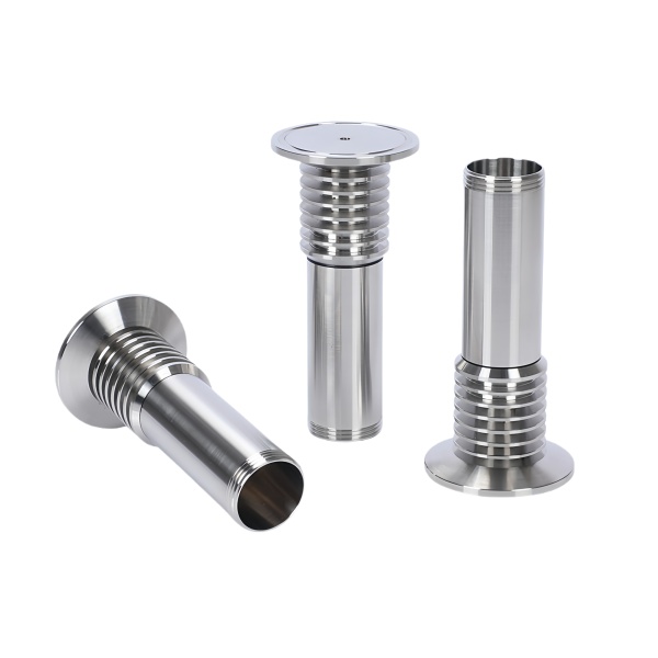
Stepped shaft runout between journals is what matters, not the runout of each diameter alone
A stepped tube or shaft—a series of coaxial diameters connected by shoulders—typically serves as a rotating element (a roller, a guide tube, a spindle) or a structural element (a liner, a spacer stack). When it rotates on bearings at two of its diameters, the dimensional parameter that controls vibration is the relative runout between the functional surfaces, measured on the bearing journals’ common axis.
We machine stepped shafts and tubes between centers (for parts with center holes) or in a single lathe setup (for shorter parts, gripped in a collet on one end, never re-chucked). Between-centers machining holds inter-journal runout to 0.005 mm TIR for lengths up to 500 mm. Single-setup turning holds 0.003 mm TIR for lengths up to 150 mm. Both methods keep the entire geometric error budget in the workpiece datum structure rather than in the fixture, which is what matters when the customer will install the part on its own bearings.
Wall thickness variation in stepped tubes determines whether thermal gradients bend the part
A stepped tube with a thin wall (typically < 3 mm) that is thicker on one side than the other will bow when heated unevenly, because the thick side has more thermal mass (lags in temperature) and more material (expands more in absolute terms). In precision apparatus—an optical bench tube, a printer roller, a sensor probe guide—this bending appears as drift in the machine's alignment as it warms up.
We control wall thickness variation to 0.05 mm max (measured at four angular positions × three axial stations with an ultrasonic thickness gauge or ball micrometer). For tubes machined from solid bar, this is achieved by rough-boring, stress-relieving (2 hours at 300 °C for austenitic stainless steel), then finish-boring with light passes. The stress-relief step matters: boring removes asymmetric residual stresses from the bar’s original processing, and without relief the tube bows after the final cut as the remaining stresses rebalance.
Shoulder squareness and the transition radius control fatigue life under rotating bending
Every step in a stepped shaft is a fatigue-relevant feature: a shoulder where the diameter changes creates a stress concentration, and if the shoulder also locates a bearing or a spacer, it sees contact pressure on its face. Two geometric parameters determine the stress concentration factor (Kt): the transition fillet radius and the shoulder face squareness.
We machine fillet radii of 0.25–0.5× the small-end diameter at every step (e.g., R2.5–5 mm for a step down to 10 mm). Sharp corners (R < 0.5 mm) at steps raise Kt to 3.0+ and are the most common root cause when a stepped shaft fails by fatigue at a shoulder rather than at a keyway or thread. The shoulder face is machined perpendicular to the axis within 0.01 mm per 10 mm of face diameter—both to distribute bearing contact evenly and to avoid bending stress superposition on the fillet.
Material selection between 304, 316, and 17-4 PH for stepped tubes and shafts
The service environment and stress level determine the grade:
- 304: General purpose, moderate strength (yield ~215 MPa annealed). Adequate for guide tubes, spacers, and low-stress shafts in dry or oil environments. Lowest cost.
- 316: Same strength class as 304 with chloride resistance. The choice for anything touching seawater, brine, or chlorinated washdown. Also the default for food and pharma contact surfaces.
- 17-4 PH (H900): Yield ~1170 MPa—5× the austenitic grades. Required when the stepped shaft transmits torque or carries bending load sized for the smaller diameters. Machines in the annealed condition, then ages at 480 °C with ~0.05 % dimensional shrinkage (we pre-compensate critical diameters). Not for service above 300 °C or in strong chloride environments.
For long tubes where straightness matters, we also consider 416 or 17-4 in the cold-drawn condition: cold-drawn bar arrives straighter and stays straighter through machining than hot-rolled austenitic bar, which contains more residual stress.
How we verify stepped tubes and shafts before shipping
Final inspection protocol:
- Runout: Part rotated on V-blocks or between centers; dial indicator on each functional diameter. Acceptance: total runout between journals ≤ 0.005 mm (precision) or ≤ 0.01 mm (standard). Recorded per diameter on the inspection report.
- Diameters: Micrometer at two angular positions per journal; OD tolerance per drawing (typically h6 or h7). Bores (for tubes) checked with inside micrometer or air gauge.
- Wall thickness (tubes): Ultrasonic or ball-micrometer at 4 × 3 stations; variation ≤ 0.05 mm.
- Shoulder faces: Squareness (indicator on face while rotating on axis) ≤ 0.01 mm per 10 mm face diameter; surface finish Ra ≤ 1.6 µm (bearing locator faces).
- Straightness (long parts): On a surface plate with the part supported at the Airy points (2/9 of length from each end for minimum deflection); indicator sag measured along the length; acceptance: ≤ 0.05 mm for parts to 500 mm, or per drawing.
- Surface finish: Journals and seal lands Ra ≤ 0.4 µm (ground) or ≤ 0.8 µm (turned with wiper insert); non-functional surfaces Ra ≤ 3.2 µm.
Our CNC Machining Parts range is where this part sits. The cnc machining parts pages carry the process notes, common materials and inspection points behind every product in the family.
Internal bore finish for sliding and sealing surfaces
A stepped tube or shaft often has a bore or journal that must slide or seal, and the as-turned surface is rarely good enough. We decide between reaming, honing, and boring from the function: a sealing bore gets a honed finish and a controlled size, a light journal may only need a sharp reamer. The finish is specified as a Ra target tied to the seal or bearing it meets, not as a generic smooth, because over-finishing a non-critical bore just adds cost while under-finishing a sealing bore leaks. We call out the finish on the feature that needs it and leave the rest at the turned value.
Marking and traceability on small tubular parts
Stepped tubes are easy to mix when they are small and similar, so we laser-mark a lot and a revision on a flat shoulder rather than relying on the bag label. The mark survives plating and handling and lets a line confirm the part before it goes into an assembly. We keep the mark clear of any sealing or bearing surface so the identifier never becomes a leak path, which is the detail that separates a useful mark from a harmful one.
Specifications
| Item | Stainless Steel CNC Machined Stepped Tubes and Shafts |
|---|---|
| Brand | AUNOV |
| Designing | A drawing file or a physical sample starts the review, a manufacturability review comes back with the quotation. |
| Tooling | Our own toolroom designs and builds every die, held under your part number. |
| Samples | Approval samples ship with dimensional data and material certification. |
| Materials | 304 / 316 stainless steel is the primary stock for this part, alongside carbon steel (SPCC / DC01), aluminium, brass and copper, with the final grade confirmed at the drawing review. |
| Surface finish | Zinc, nickel or chrome plating, e-coat, powder coat, anodising or passivation, each selected against the drawing requirement. |
| Processing | Stages of deep drawing, annealed in line where the draw ratio calls for it, then pierced and CNC-machined under our own roof. |
| Equipment | Presses run 5-250 T mechanical and 250-500 T hydraulic, with CNC turning centres and a climate-controlled CMM room for inspection. |
| Tolerance | As-drawn tolerance +/-0.1 mm, +/-0.03 mm on machined features. |
| Delivery terms | Standard terms FOB, DDP offered to EU and US, T/T and L/C accepted, D/P for established customers, blanket orders and call-offs supported. |
Related Products


Request a Quote for This Part
Send a drawing or sketch — get material advice, tooling cost and a per-piece price within 24 hours (working days).