
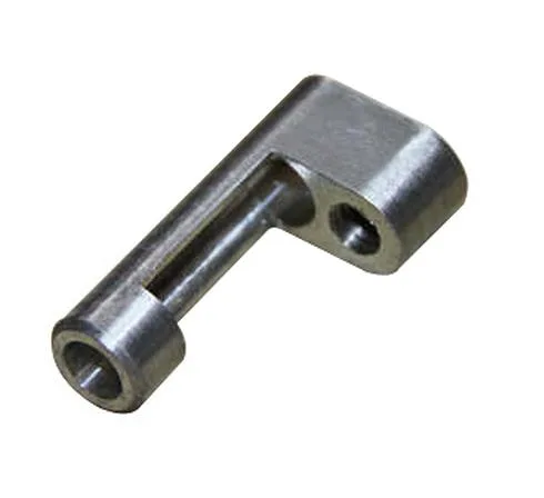
A punch is the simplest object in this catalogue and one of the hardest to make well. It is a hardened piece of steel with an edge, and its entire job is to concentrate a very large force onto a very small area, repeatedly, for millions of cycles, while the rest of the tool holds it. That combination – extreme local stress at a very small geometry, in a material that is hard enough to resist wear and therefore difficult to shape – is what makes punch making a discipline rather than an operation.
The tolerance on this part is stated as +/-0.01 mm on critical bores. That number is worth pausing on, because for a punch the interesting dimensions are usually not bores at all. They are the edge’s geometry, and they are held in microns, and they are the reason the part is difficult.
The edge, which is the entire specification
A punch’s working edge has a defined shape that depends on what it is punching, and getting the shape right is most of the engineering.
- A radius, not a sharp point. A punch that punches a hole in sheet needs a radiused edge, and the radius determines the hole’s quality. Too small and the punch will chip or roll over at the edge under the shear load. Too large and it will produce a hole with poor edge quality and excessive burr. The radius is a specific, calculated dimension.
- The end profile. Flat, domed, or stepped, and each produces a different sheared-edge characteristic. On a punch that forms rather than shears, the profile is the forming geometry and is even more tightly specified.
- The clearance angle and the land. A punch that shears material needs an angle of clearance so that the punch does not rub on the hole it is cutting through the whole stroke, and a land at the end that progressively shears rather than trying to shear the full thickness at once. This is where most of a punch’s design knowledge lives and it is entirely invisible on a dimensioned drawing.
- The radii where the working section meets the shank. On a stepped punch – a small working end on a larger shank – the transition is a stress concentration under cyclic bending, and it is where a punch breaks. The radius there is a life-determining dimension.
So the honest statement about a punch is that the drawing gives the envelope and the supplier supplies the edge geometry from standard practice. Which is reasonable, provided the edge geometry is at least specified as a requirement – the radius, the end condition, the clearances, and the surface finish of the working edge – rather than left entirely to convention.
Material, and the reason it is hardened and then ground
The material has to be harder than the workpiece, and the workpiece may be mild steel, stainless steel, spring steel or aluminium. The sequence on a punch is essentially fixed by physics:
- Machine it soft. Tool steel in the annealed or normalised condition machines predictably and does not work-harden on the surface. Every serious punch is rough-machined before hardening for this reason, and a punch that is hardened first can only be finished by grinding, which is slow and expensive.
- Harden it. Through-hardening is straightforward for a small solid punch and it is what gives the edge its wear resistance. Vacuum hardening is used where the part has any risk of decarburisation or distortion, and on a punch the edge is the thing that must not be damaged, so vacuum or atmosphere-controlled hardening is worth specifying where the geometry or the quality requirement warrants it.
- Temper it. This is the step that is easy to skip in conversation and it is not optional. Hardened tool steel at full hardness is brittle; tempering trades some hardness for a large gain in toughness, and a punch that is not adequately tempered will chip rather than wear. The hardness specification and the temper are one decision.
- Finish grind it. After hardening the part has changed size – distortion during hardening – and the edge must be ground. Grinding is what holds the edge’s geometry and its surface finish, and it is the operation that produces the microns.
The practical consequence for a drawing is that a punch’s as-machined dimensions and its finished dimensions are different, and the finished ones are the ones that matter. Every dimension on a punch should be understood as a post-grind dimension unless stated otherwise, and any dimension that will be disturbed by heat treatment should be held on a sacrificial stock allowance – a shank long enough to be held in the machine and ground back – which is a standard feature of punch design and worth asking about.
Dimensional control, and where the microns go
There are three distinct tolerance regimes on this part, and conflating them is the usual reason a punch drawing is unusable.
- Critical bores and mounting features, at +/-0.01 mm. This is where the punch is held in the tool holder. The shank’s diameter and its roundness determine how the punch is centred, and a punch that is 0.02 mm off-round in the shank will produce a hole that is off-position and it will produce the same off-position hole every stroke. This is the tolerance band that justifies machining.
- The working end’s geometry, in microns. The edge radius, its consistency along the perimeter, and the profile’s relationship to the punch’s axis. On a small punch the edge radius may be a fraction of a millimetre, and holding it consistently around the circumference is a grinding problem, not a turning problem.
- The general envelope, at a general tolerance. The punch’s overall length, its shank’s length, its body diameter where it is not a functional fit. These do not need tight control and holding them tightly is wasted money.
Turn-mill machining with critical diameters finished in one setup is the right route for a punch because the shank, the step and the small end are all related to one another and to the punch’s axis. A punch that has been re-chucked will not be concentric, and a non-concentric punch produces a non-round hole and a non-uniform shear load around the edge – which is a wear problem as much as a quality problem.
The wear question, which is what actually ends a punch’s life
A punch does not usually fail by breaking in service. It usually fails by wearing, and it wears by two mechanisms at once, which is why the wear pattern on an old punch is informative.
- Abrasive wear, where the workpiece’s edge or its inclusions cut the punch’s edge. This is why a punch working on mild steel lasts longer than the same punch on stainless steel or on aluminium with high silicon content – the workpiece is harder than people expect. Galling and material transfer are a related phenomenon: a galling punch picks up material and the edge grows, and it will then punch a hole with a burr that grows until it fails.
- Edge rolling and chipping, where the repeated impact work-hardens and deforms the very edge until it breaks off. This is the toughness problem, and it is the reason for adequate tempering and for a sensible edge radius.
- Galvanic or adhesive pickup where dissimilar materials are involved in the sliding contact at the land.
And one more that is easy to overlook: the clearance is a life parameter. A punch with insufficient clearance rubs on the hole wall for the whole stroke, generating heat and wear even when it is not shearing. A punch with generous clearance shears cleanly and wears slowly. This is the single cheapest life improvement available on a punching tool, and it costs nothing but a decision.
Surface finish of the working edge, and the functional finish elsewhere
Plating, powder coating, anodising or polishing per the print, with the agreed finish travelling with the part number. On a punch, the finish question is almost entirely about the edges and about the surfaces that rub.
- The working edge is normally left ground and unplated. A plated edge is a softer edge and a plated edge does not hold its geometry. This should be stated explicitly, because a general plating callout on a punch drawing is a mistake and it will produce a punch that dulls quickly.
- The shank is where a plating or a coating is sometimes applied – a hard chrome on the shank improves its slide fit in the holder and its galling behaviour against the holder. That is a legitimate wear decision and it is a different one from plating the edge.
- The surface finish on the working land is functional in the other direction: it controls friction and therefore heat. A very highly polished land can polish the hole wall and reduce galling, and a rougher land generates more heat. Where a punch runs at volume with a marginal clearance, this is a real variable.
- Any non-functional surface can be coated or plated for appearance or for handling, and the masked areas should be named.
Other mould components, and the shared logic
This page covers punches and mould components generally, and the things they share are worth stating because they make the whole family easier to specify.
- Stripper components – springs, strippers, punches to punches. The same hardness and toughness logic applies, and spring temper is a specific and important requirement.
- Dies and die buttons – the cutting edge is again the specification, and again the edge must be ground after hardening.
- Guide pins and bushes – these are a wear pair rather than a cutting edge, and their requirement is wear resistance plus a sliding fit, which is a different tolerance philosophy: the fit is what matters and it will change in service, so some allowance for that is usually appropriate.
- Locating and reference parts – these are hardened and ground and their requirement is positional accuracy that does not drift. On a reference part, hardening distortion and the grinding that follows it are the whole game.
The common thread across all of these: the part is machined soft, hardened, tempered, ground, and its life depends on two design decisions the drawing usually does not record – the clearance, and the edge radius. Both are worth a conversation, and both cost nothing.
Edge profile needs an optical comparator, not a visual check
- Critical bores and shank diameter and roundness at +/-0.01 mm, on the CMM, on every part or a stated frequency.
- Edge geometry – radius, profile, and the consistency around the circumference – measured with an optical comparator or a profilometer, not visually.
- Hardness and case depth, on every heat and on the first article of each lot. Hardness is cheap to check and it is the difference between a punch that lasts and one that chips.
- Temper verification, by hardness, on the same basis.
- Edge surface finish where it is specified.
- Finer bands confirmed from capability data before quoting, and where a band is genuinely beyond normal capability, the conversation belongs at the DFM stage rather than after the first article is out.
- A functional punch test on the first article, on the actual workpiece material. A punch’s quality is best judged by the hole it produces and by how it looks after a defined number of strokes. This test also catches clearance and geometry problems that no amount of dimensional inspection would reveal.
The material, the thickness and the daily strokes
What is the punch actually punching – what material, what thickness, and how many strokes a day? Those three numbers determine the working length of the punch, which determines the material, which determines whether it should be through-hardened or case-hardened, and they determine whether the clearance needs to be generous because the tool runs continuously or tight because the tool is intermittent. They also determine whether this part is a standard item with a modified detail or a purpose-designed tool. A punch quoted without knowing the material and the stroke count is a guess, and the guess usually shows up as either a punch that chips or a punch that was over-specified and cost more than it needed to.
Parts like this one sit under the CNC Machining Parts range, whose overview page gathers the tooling logic, finishing options and tolerance notes shared across the family.
Specifications
| Item | Steel L-Shaped Machined Arm with Cross Bore |
|---|---|
| Brand | AUNOV |
| Designing | Driven by your drawing or a physical sample – DFM notes are returned before any tooling is cut; the agreed version governs every later batch. |
| Tooling | Progressive and drawing dies are designed and built in house, so no tooling step is outsourced, and the die remains dedicated to your part. |
| Samples | Sample parts are measured and reported before submission, so the approved first article becomes the gauge reference, and mass production is gated on that approval. |
| Materials | Stock covers carbon steel (SPCC / DC01), 304 / 316 stainless steel, aluminium and brass; the final grade is fixed with the drawing review. |
| Surface finish | Plating, powder coating, anodising or polishing, per the print; the agreed finish travels with the part number. |
| Processing | Turn-mill machining, critical diameters finished in one setup; every stage is logged against your part number. |
| Equipment | CNC turning centres with bar feeders and 3-/4-axis machining centres, with in-house toolmaking to keep dies and fixtures maintained. |
| Tolerance | +/-0.01 mm on critical bores, confirms at DFM stage; finer bands confirmed from capability data before quoting. |
| Delivery terms | FOB, CIF or DDP per Incoterms 2020, T/T or L/C, with D/P accepted on repeat business; call-off schedules are supported. |
Related Products



Request a Quote for This Part
Send a drawing or sketch — get material advice, tooling cost and a per-piece price within 24 hours (working days).