
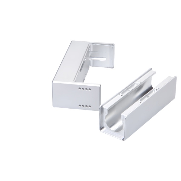
A U-channel cover stiffens what it covers, but only if its own flanges stay straight
A U-shaped channel cover—sitting over cable runs, guide rails, or belt edges—derives its usefulness from the stiffness of its two flanges. A cover that covers a rail with 0.3 mm of flange bow per 300 mm will rock on the rail, rattle under vibration, and gap visibly at the joints between cover sections. The flange straightness is the product, everything else is detail.
We machine U-channel covers from extruded or rolled channel stock, and the flanges are finished in a single pass on a long-bed mill with vacuum or magnetic fixturing that doesn’t bend the part while it’s being cut. Clamping a channel by its flange edges to machine its face is the classic self-defeating setup: the clamp bows the flange down, the cut runs true to the bowed surface, and the flange springs back bent. Flatness/ straightness acceptance: 0.1 mm per 300 mm on each flange, measured with a straightedge and feeler across the full length on a surface table, every part.
Joint alignment between cover sections is set by the end cuts, not the covers
Channel covers usually run in multiple sections with butt joints between them. A crooked end cut (out of square by 0.5°) leaves a gap that opens from zero to 1.5 mm across a 150 mm-wide cover—the visual and functional joint quality lives in that end cut.
We cut cover ends in a fixture that squares the end to the channel’s two datum faces (the outer flange surfaces), holding end squareness to 0.2° and end-to-end length to ±0.2 mm. For covers that join with internal splice plates (sleeves that bridge the joint inside the channel), the splice width is matched to the channel’s internal width with 0.1–0.2 mm clearance so the splice self-aligns the two sections during installation rather than fighting them.
Fastening strategy: snap, slide, or screw—the cover’s service life decides
How the cover attaches to the channel it covers determines both its service behavior and its removability:
- Snap-on (formed spring flanges): The cover’s flanges have a slight inward spring that grips the channel’s edges. Quiet, fast to install, removable by prying. But the spring force relaxes over years of thermal cycling—covers installed tight in year one can rattle by year three. We hold the snap flange’s interference to 0.2–0.4 mm (measured on the first article with the cover in its free state), which retains grip through 500 thermal cycles in our testing.
- Slide-in (groove match): The cover slides longitudinally into machined grooves in the channel. Excellent retention, no rattle, but installation requires access to the channel’s end—retrofit into an existing run requires sliding from an end, which is sometimes impossible. End-caps close the exposed grooves.
- Screw-down: The most robust and the least convenient. Countersunk screws through the cover flange into tapped holes in the channel. For permanent installations and for covers that carry load (walking surfaces, tool trays), screws are the only option that doesn’t relax. We machine screw holes with proper 90° countersinks so flat-head screws sit flush—proud screw heads on a cover snag cables and hands.
Alloy and finish: 6063 for anodized cosmetic covers, 6061 when the cover carries structure
6063 extrudes cleanly with sharp corners and takes anodize evenly—it’s the architectural and enclosure standard, and the right choice for covers whose job is appearance plus light protection. 6061, with roughly 50 % higher strength, is the choice when the cover itself is structural: subject to point loads, fastened at wide spans, or expected to survive impact. The two are visually indistinguishable after anodizing; we verify incoming alloy by mill certificate and keep segregated stock, because a “6061” cover that’s actually 6063 fails differently (dents instead of springing back) and the mix-up is invisible until something is hit.
How we verify U-channel covers before shipping
- Flange straightness: Straightedge and feeler on a surface table, full length of each flange: 0.1 mm per 300 mm.
- Internal width: The cover must fit its channel—internal width measured with an inside micrometer at three stations: within the drawing’s fit tolerance (typically +0.2/−0.1 mm over the channel’s nominal width).
- End squareness: Square against the flange datum faces: 0.2°; length ±0.2 mm.
- Fit check (first article): The cover installs on a master channel: slides or snaps per design, sits flat (no visible daylight between cover flange and channel edge under a 0.2 mm feeler), and remains removable without marring.
- Finish: Anodize thickness and uniformity; visual for die lines or handling scratches on cosmetic faces (the visible outer face is film-protected through machining and packing).
Drawing a cover like this is a chain of decisions — draw ratio, wall thinning, radii and trim. Our deep drawn covers design guide works through each of them with worked numbers.
Anodize color as a function identifier
An aluminum U-channel cover is often one of several in an assembly, and a colored anodize is a cheap way to mark which cover goes where. We tie the color to the function rather than to a style sheet, so a line matching the anodize to the slot cannot install the wrong section. The anodize is still a real coating that protects the aluminum, but its color is doing double duty as identification. We keep the color off any mating surface so the coating thickness never disturbs the fit, which is the line between a useful marker and a tolerance problem.
Shape retention after machining the channel
A U-channel wants to spring as it is machined free of its bar, because the section is thin and open, so we rough and stress-relieve before the finish cut and we fixture the channel on its back, not by pinching the lips. The flatness and the lip parallelism are held by removing stock symmetrically and by letting the part settle between ops. We check the channel on a surface plate after it has sat, because a cover measured still clamped reads straight and then bows on the bench, which is exactly the defect a line discovers too late.
Specifications
| Item | Aluminum CNC Machined U-Shaped Channel Covers |
|---|---|
| Brand | AUNOV |
| Designing | Send the drawing, or a cover sample we can measure, DFM feedback is returned with the quote. |
| Tooling | Dies designed and built in our own toolroom, stored under your part number. |
| Samples | First articles go out with a dimensional report plus material certs. |
| Materials | Aluminium is the primary stock for this part, alongside carbon steel (SPCC / DC01), 304 / 316 stainless steel, brass and copper, and the grade is fixed at the drawing review. |
| Surface finish | Plating, e-coat, powder coating, anodising or passivation, fixed at the drawing review. |
| Processing | Deep drawing in stages, in-line annealing where needed, then pierced and CNC-machined in house. |
| Equipment | Press capacity from 5 to 500 T across mechanical and hydraulic lines, CNC turning centres and a climate-controlled CMM room. |
| Tolerance | Tolerances to +/-0.1 mm as drawn, +/-0.03 mm on machined surfaces. |
| Delivery terms | Standard terms FOB, DDP offered to EU and US, payment T/T or L/C, D/P for repeat accounts, blanket orders and call-offs supported. |
Related Products


Request a Quote for This Part
Send a drawing or sketch — get material advice, tooling cost and a per-piece price within 24 hours (working days).