
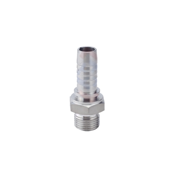
On a barb-thread adapter, the barb’s crest radius is a wear part—inspect it, don’t assume it
A hose barb thread adapter—male or female thread on one end, barbed tail for hose on the other—holds its hose by the barbs’ crests digging into the hose liner. The crest radius is set by the forming or machining tool, and it wears: as the tool dulls, crests round over from a designed 0.05–0.1 mm radius to 0.2 mm or more, at which point the barb slides rather than bites, especially on stiff hoses (fluoroelastomer, PTFE-lined).
We machine barb profiles with a profile-ground form tool, and we control crest radius by tool-life limits: the tool is changed every N parts (established per design) or when the crest-radius check on a sampled part exceeds 0.12 mm. The check is quick—a profile projector comparison against the drawing’s barb profile at 20×—and it’s the difference between a shipment of adapters that hold and a shipment that blow off hoses on the test bench.
Barb spacing and hose-wall compression: the design window between slip and cut
Adjacent barbs must compress the hose wall enough to grip but not so much that the crest cuts into the hose’s reinforcement. The working number is the radial interference between barb major diameter and hose inner diameter, expressed as a percentage of hose wall: 10–20 % compression grips reliably on rubber hoses; above 25 %, the barb crest starts to sever the textile or wire reinforcement, and the hose fails at the barb under pressure cycling rather than in free span.
When a customer specifies a hose we haven’t paired with a barb design, we section a sample: a cut hose-on-barb cross-section shows exactly where each crest sits in the wall. Ten minutes of sectioning at the prototype stage has repeatedly prevented a full production run of adapters that were one size too aggressive for the specified hose.
The thread-to-barb junction takes the hose’s bending load, so it needs a generous shoulder
In service, the hose hangs off the barb and bends; the bending moment reacts at the junction between the hose’s clamped end and the adapter’s rigid thread body. A sharp step there (the end of the barb tail meeting the thread’s shoulder) concentrates all hose bending stress into the hose’s first clamped millimeter, and hoses crack in fatigue precisely at that line.
We machine a smooth transition at the barb root: the last barb runs out into a tapered land (8–12° half-angle) that lets the hose’s stiffness ramp up over several millimeters instead of stepping abruptly. Adapters with the runout land show a 5–10× improvement in hose bend-fatigue life over sharp-shoulder designs in our customers’ vibration testing—almost free (one extra pass in the form-tool path) for a failure mode that dominates warranty claims on hose assemblies.
Thread seal and hose clamp act as a system: specify both, test both together
The adapter has two seals—the thread side and the barb side—and a leak is a leak, whichever side it comes from. The barb side’s seal depends on the clamp (constant-torque clamps hold their preload under thermal cycling; worm-drive clamps relax and are the source of most slow weeps on heated hose systems). The thread side depends on its seal method (dryseal, sealant, or O-ring boss).
Our production test assembles the adapter the way the field will: specified thread seal method, specified clamp type torqued to the clamp’s spec, then pressure-cycles the assembly (10 cycles 0→1.5× rated) while immersed. Every batch, one assembly. Failures trace to their side of the adapter, and the finding goes back to the drawing or the installation sheet—half the “barb failures” we investigate trace to a worm clamp that relaxed, not to the machined barb.
How we verify barb thread adapters before shipping
- Thread: Go/no-go per class, 100 % of parts.
- Barb profile: Profile projector on first article and every 25th part: major diameter, crest radius, barb spacing, root diameter, runout land angle. Any crest-radius drift beyond 0.12 mm triggers a tool change.
- Concentricity: Barb tail-to-thread axis, 0.05 mm TIR on the lathe (single-setup machining keeps this natural, but the check catches collet wear).
- Bore (if flow-through): Plug gauge; bore chamfer visual.
- Assembly test (one per batch): Specified hose and clamp, 10 pressure cycles at 1.5× rated while immersed, plus a pull-off test at 1.5× the hose’s rated pull force. Zero slip, zero leak, zero hose severance at any barb.
This part belongs to our CNC Machining Parts range. The cnc machining parts pages collect the process notes, common materials and inspection points behind every product in the family.
Hose compound compatibility with the barb finish
A barb holds a hose by biting its way into the rubber, and the barb finish decides whether the hose grips or tears. We match the barb crest radius and the surface to the hose compound, because a soft silicone needs a different bite than a stiffed hydraulic line, and a sharp crest slits a fragile hose while a dull one slips. The barb is cut so the hose compresses into the valleys without the crest cutting through, which is why the adapter is specified against the hose it will see rather than as a generic thread-plus-barb. We note the recommended hose family on the drawing so the joint is selected, not assumed.
Field torque limit on the barb side
The hose clamps on the barb side, not the thread, so the clamp torque, not the adapter, sets the hold. We state a clamp range and warn against over-tightening, because a clamp cranked past the barb crest cuts the hose and a clamp left slack lets it walk off. The thread side takes the line pressure and is torqued to its own spec; the two are independent and we label both so a technician does not treat the barb like a threaded seal. A barb joint that fails almost always failed at the clamp, not at the adapter.
Specifications
| Item | Stainless Steel CNC Machined Hose Barb Thread Adapter |
|---|---|
| Brand | AUNOV |
| Designing | A drawing file or a physical sample starts the review, DFM feedback is returned with the quote. |
| Tooling | Dies engineered and produced in our own toolroom, stored under your part number. |
| Samples | The first-article set ships with a full dimensional report and mill certificate. |
| Materials | 304 / 316 stainless steel leads the stock list for this part, alongside carbon steel (SPCC / DC01), aluminium, brass and copper, per the drawing. |
| Surface finish | Zinc, nickel or chrome plating, e-coat, powder coat, anodising or passivation, fixed at the drawing review. |
| Processing | Multi-stage drawing, annealed in line where wall thinning calls for it, with piercing and finish machining under the same roof. |
| Equipment | Press capacity from 5 to 500 T across mechanical and hydraulic lines, CNC cells plus a temperature-controlled CMM room. |
| Tolerance | +/-0.1 mm on as-drawn features, +/-0.03 mm on machined features. |
| Delivery terms | Prices FOB, with DDP for EU and US on request, payment T/T or L/C, D/P for repeat accounts, call-off schedules supported. |
Related Products


Request a Quote for This Part
Send a drawing or sketch — get material advice, tooling cost and a per-piece price within 24 hours (working days).