
Five axes exist to avoid a second setup, and they are worth paying for only when the geometry demands it
A five-axis machined part is a part whose features point in enough different directions that a three-axis machine would have to be re-fixtured to reach them. That is the honest definition, and it matters more than the axis count itself, because five-axis capability is a solution to a specific problem and a cost when the problem is not there. The useful question on any part is not how many axes are available but how many setups the geometry actually requires.
We sequence turning, milling and drilling to minimise handling and re-chucking, and every stage is logged against your part number, on CNC turning centres with bar feeders and 3- and 4-axis machining centres, with in-house toolmaking keeping dies and fixtures maintained. General tolerance is +/-0.02 mm with tighter bands on flagged dimensions, and dimensional reports accompany the first article. Stock covers carbon steel in SPCC and DC01 grades, 304 and 316 stainless steel, aluminium and brass, with the final grade fixed at the drawing review. Plating, powder coating, anodising or polishing per the print, with masking and laser marking available where needed. This page is about what five axes actually solve, what they cost, and the four situations where they are the right answer.
What the extra axes really are
A three-axis machine can only move its tool linearly along three directions relative to the part. A five-axis machine can rotate the tool or the part about two additional axes, which means:
- Approach from a direction, not just along an axis. A five-axis machine can cut a feature on a face that points sideways, or upward, or at an angle, without the part being reoriented to present that face to a three-axis spindle. This is the core capability and it is what eliminates setups.
- Simultaneous multi-axis motion. On a simultaneous machine the tool follows a continuously changing path while the part is held in one clamping. This is what enables a complex 3D form to be machined without re-fixturing, and it is a different capability from simply having more reach.
- Much greater tool reach and a smaller machine for a given part size. A five-axis machine can machine a large part in a small machine, because it swings its head rather than needing the part to move.
So the distinction that matters in practice is between a five-axis machine used in simultaneous mode – where the value is a complex form machined in one setup – and a five-axis machine used in indexed or positional mode – where the value is simply reaching more directions with fewer setups. The second is much more common and much less dramatic, and it is usually what a part actually needs.
What each avoided setup is worth
Every re-chucking is a cost, and four of the five are real costs rather than annoyances:
- Accuracy. Each re-chucking introduces a new datum. A feature machined in a second setup is no longer related to a feature in the first setup by the machine’s accuracy – it is related by where the operator put the part. On a part with cross-feature position requirements, every setup is a tolerance stack.
- Error accumulation. Angular errors, the part’s movement in the fixture, and clamping that distorts the work all feed into the next operation’s result. On a thin or delicate part the distortion from one clamping is often not recoverable in the next.
- Time. An operator loading, aligning, clamping, and starting a second operation is minutes, and on a small part it is the dominant part of the cycle. On a high-volume part this is the whole economic argument for five axes.
- Handling and damage. Every transfer is a chance to mark a finished surface, to chip a burr, or to drop a part. On a small machined part, handling is where the parts are actually lost.
So the value of a setup avoided is large on an accurate part with cross-feature requirements, large on a high-volume part, and small on a low-volume part whose features are not related to each other. That is the calculation behind whether five axes pays on a given job – and it is worth doing explicitly rather than assuming the machine with more axes is the better answer.
Four situations where five axes is clearly right
| Complex 3D forms | A part whose whole surface is a smooth 3D form – an impeller, a turbine housing, a medical manifold, an aerodynamic fairing. These are machined in one setup because re-fixturing a curved form is not possible without a fixture that would distort it. |
|---|---|
| Deep cavities on several faces | A part with pockets and bores on four or five different faces. A three-axis machine needs four or five setups, and each re-orientation is an accuracy stack. This is the most common industrial application of five axes and it is a clean engineering argument. |
| High-volume small parts | Where the setup time dominates. Here the machine pays for itself in labour reduction, and the design is usually a prismatic part that is conventional to machine but expensive to handle – the classic case where five axes on the part is five axes justified by the production economics. |
| Thin or delicate parts | Where clamping between operations would distort the work. A thin-wall part that must be machined on both sides cannot be re-chucked without a deformation the design cannot tolerate, so the single setup is not a convenience – it is the only way to make the part. |
And the situations where it is not right, which are just as common:
- A prismatic part with features on three faces. Three setups on three-axis is straightforward, accurate enough, and much cheaper per part. Five axes here is a solution to a problem the part does not have.
- A low-volume prototype. The programming and fixturing for five axes is more complex and slower to set up, and at a dozen parts the setup cost is not amortised at all.
- A part with no cross-feature relationships. If the features do not need to be related to each other, each can be machined in its own setup at no accuracy cost, and three-axis is the cheaper machine.
What five axes do not solve
Three limitations worth stating, because they are commonly assumed to be solved by having more axes:
- It does not improve accuracy. A five-axis machine is not more accurate than a good three-axis machine; it is a well-built machine with the same fundamental accuracy. What it improves is the relationship between features machined in one setup, because that relationship is the machine’s. If the requirement is absolute accuracy rather than relative accuracy, the answer is a better machine or a grinding operation, not more axes.
- It does not improve tool life. The cutting conditions are the same. A five-axis machine that is fed a program with aggressive parameters will wear its tools exactly as fast.
- It does not remove the need for a decision about datums. In a five-axis program the part’s coordinate system is still the datum scheme, and the CAM programmer still has to decide where the part’s origin is. More axes does not make that decision go away – it just moves it earlier into the process.
Material, and what the geometry requires
Stock covers carbon steel in SPCC and DC01 grades, 304 and 316 stainless steel, aluminium and brass, with the final grade fixed at the drawing review. On a part that may be five-axis machined, the material choice is driven by the geometry’s machinability rather than by the process:
- Aluminium 6061 is the most common material for a five-axis part and for a good reason: it machines fast, it is well-behaved, and its good surface reduces the finishing requirement. 6061 is the machinability grade and it is the default for a complex aluminium form.
- 304 and 316 stainless steel where corrosion resistance or a specific appearance applies. Stainless Steel is slower to machine and more prone to work-hardening, and on a complex 3D form the interrupted cuts of a five-axis program make the work-hardening worse – so a free-machining variant is worth considering where the geometry allows.
- Carbon steel where cost governs and the environment is mild; the free-machining grades are a genuine economy on a complex part because cycle time dominates.
- Brass where a specific corrosion behaviour or a fine surface applies, and it machines well enough that the process is comfortable.
Masking complex geometry is harder than masking a flat face
Plating, powder coating, anodising or polishing per the print, with masking and laser marking available where needed. Three points on a part with complex geometry:
- Masking on a complex part is more difficult, because access to a surface inside a cavity or underneath an overhang is limited. On a five-axis part the masking should be designed with the geometry in mind – a part that cannot be masked cleanly will have a finishing variance, and on a visible part that shows.
- Surface finish on a machined 3D form follows the form. A machined surface has a tool-mark pattern that follows the tool’s path, and on a complex form that pattern is visible. If the part is cosmetic, the finish specification and the machining’s tool paths need to be considered together, and a fine surface finish specification is often worth more than a finer machining.
- Passivation on stainless steel and anodising on aluminium are dimensionally well behaved, which on a part with many tight features is a real advantage over plating.
Setups are what the geometry is really costing
Eight things, and the first is the one that determines whether five axes is justified at all:
- Whether the part must be machined in one setup, and if not, which features may be machined in separate setups. This is the requirement that decides the process, and it should be stated as a requirement rather than assumed.
- Which features are related to which, and by what tolerance – and where that relationship only has to hold within one setup, the tolerance structure becomes much cheaper.
- The datum scheme, named, so the relationship between features is defined rather than emerging from the program.
- General machining at +/-0.02 mm, with the flagged dimensions identified, and tighter bands on the features that are truly critical.
- Any feature that is only accessible from one direction, and any feature that would need re-fixturing on three axes – because those are the features that justify the machine.
- Surface finish requirements on any cosmetic surface, and the tool-path direction where that matters.
- Material grade, chosen for the geometry’s machinability as much as for the duty.
- Masking, and whether the geometry allows it, with dimensions stated before or after finish.
How many setups does this part actually need?
Direct answer: This question feels like a retreat from the modern answer and is in fact the opposite – it is how you find out whether the modern answer is the right one. A part that genuinely needs five setups is a better part for five axes: fewer operations, better accuracy between features, less handling. A part that needs two or three is better for three axes: cheaper machines, simpler programming, faster setup, and an accuracy cost that the design may well tolerate. Establishing which of those two parts this is takes one question at the design stage, and it is worth far more than the machine’s axis count.
When is a five-axis machine actually the right choice?
Direct answer: When the features point in enough directions that a three-axis machine would have to re-fixture the part to reach them. That is the honest definition. It is worth paying for on complex 3D forms, on deep cavities on several faces, and on parts with cross-feature position requirements, where every avoided re-chucking removes a datum transfer and a tolerance stack. It is a cost rather than a benefit when the problem is not there.
Does a five-axis machine hold better tolerances than a three-axis machine?
Direct answer: No, and that is a common misunderstanding. A five-axis machine is not more accurate than a good three-axis machine; it is a well-built machine with the same fundamental accuracy. What it improves is the relationship between features machined in one setup, because that relationship comes from the machine instead of from a fixture. If a tolerance is tighter than either machine can hold, more axes will not recover it.
This part belongs to our CNC Machining Parts range. The cnc machining parts pages collect the process notes, common materials and inspection points behind every product in the family.
Specifications
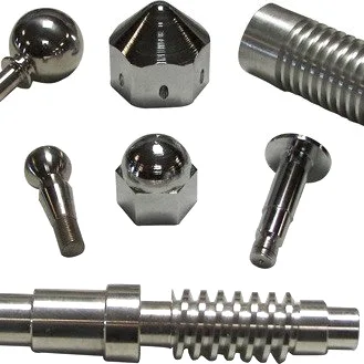
| Item | CNC Turned Domes, Knurled Rollers and Pins |
|---|---|
| Brand | AUNOV |
| Designing | Your 2D/3D files (PDF, DWG, STEP, IGS) are reviewed for manufacturability before any price is confirmed. |
| Tooling | Die design and toolmaking stay in house, so tooling lead time stays under our control, and the die remains dedicated to your part. |
| Samples | Pre-production samples come with a full inspection report, so any deviation is corrected at sample stage, and mass production is gated on that approval. |
| Materials | Stock covers carbon steel (SPCC / DC01), 304 / 316 stainless steel, aluminium and brass; the final grade is fixed with the drawing review. |
| Surface finish | Plating, powder coating, anodising or polishing, per the print; masking and laser marking available where needed. |
| Processing | Turning, milling and drilling sequenced to minimise handling and re-chucking; every stage is logged against your part number. |
| Equipment | CNC turning centres with bar feeders and 3-/4-axis machining centres, with in-house toolmaking to keep dies and fixtures maintained. |
| Tolerance | +/-0.02 mm general machining, tighter on flagged dimensions; dimensional reports accompany the first article. |
| Delivery terms | CIF or DDP, with FOB available, payment by T/T, L/C at sight or D/P; repeat orders reuse the approved first article. |
Related Products


Request a Quote for This Part
Send a drawing or sketch — get material advice, tooling cost and a per-piece price within 24 hours (working days).