
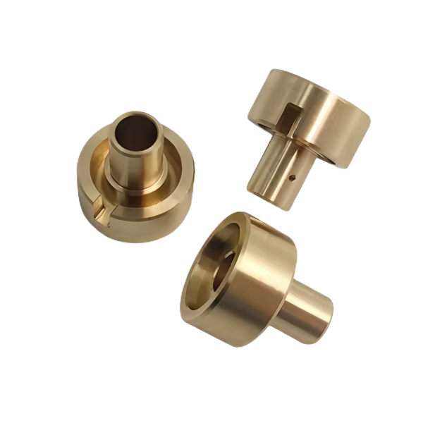
Valve body bore-to-seat concentricity is the dimensional heart of a brass valve
A brass valve body—piston valve, check valve, or needle valve body—houses a moving member (the piston, poppet, or needle) that seats against a machined seat. If the bore that guides the moving member is not concentric with the seat ring, the piston lands on the seat at an angle: one side contacts first, the seal line is partial, and the valve leaks below its rated pressure no matter how clean the surfaces are.
We machine valve bodies with the guiding bore and the seat in one lathe setup (part in a collet, bore machined, seat turned or bored, body sealed face faced—all before unclamping), holding bore-to-seat concentricity at 0.01 mm TIR. Bodies with cross ports (the inlet/outlet at 90° to the bore) get their cross-drilling in a second setup indexed from the bore’s datum axis, so port-to-bore position stays within 0.05 mm—cross-port eccentricity shows up as uneven flow between the valve’s two flow directions.
The piston’s diameter tolerance, not its material, sets the leakage class
A valve piston fits its guiding bore with a clearance that is the valve’s leakage path: too tight, the piston binds when temperature shifts or debris passes; too loose, the valve leaks internally between the pressure zones. For brass-on-brass (body C36000, piston C36000 or 304 stainless steel), the working clearance is 0.010–0.020 mm per 25 mm of diameter for low-leakage service, and 0.025–0.040 mm for general service where some bypass is tolerable.
We machine pistons to match bores, not to a paper number: bore sizes are measured on the first articles (air gauge, three stations), and the piston’s OD target is set to the measured bore minus the designed clearance. Matched-pair assembly takes one extra measurement per pair and eliminates the entire “in-tolerance parts, leaking valve” failure class—two parts can each be inside their tolerance band and still, at worst-case stacking, produce a 0.06 mm clearance that no valve spec tolerates.
Seat surface condition: where 0.8 µm versus 0.4 µm decides bubble-tight or not
The valve seat’s surface finish determines whether the piston or poppet can seal against it. A turned seat at Ra 1.6 µm has circumferential tool marks—microscopic spiral channels that the closing member cannot block; the valve “seals” until the pressure differential drops and seepage through the tool marks becomes measurable.
We finish seats with a light boring pass with a fresh insert at low feed (Ra 0.4–0.8 µm), and for bubble-tight specs (zero visible leakage at rated ΔP), the seat gets a final lapped finish (Ra 0.1–0.2 µm, verified with a surface-finish comparator or stylus on the first article). The seat is inspected for radial tool marks at 20× on every part—a single chatter mark across the seat is a leak path that no amount of piston precision will close.
Valve body cross-ports: drill breakout, burrs, and the flow path’s hidden restriction
The body’s cross ports (inlet, outlet) intersect the main bore through drilled passages. Where the drill breaks through into the bore, it leaves a burr and an irregular breakout edge—both flow restrictions and debris generators. A burr in a valve’s flow path eventually detaches, travels to the seat, and holds the valve open.
We drill cross-ports undersize, then bore them to final size through the breakout (boring removes the burr rather than folding it over), and we hand-verify each breakout with a bore scope at 10× on every body. The intersection where the cross-port meets the bore is chamfered 0.3 mm to break the sharp edge—unbroken edges at intersections are the classic stress riser where pressure-cycled bodies crack.
How we verify valve bodies and pistons before shipping
- Body: Bore (air gauge, 3 stations), seat concentricity (arbor + indicator: 0.01 mm TIR), seat finish (comparator/ first-article stylus), cross-ports (bore gauge + scope inspection of breakout), threads (go/no-go).
- Piston: OD (micrometer, 2 angular positions × 2 stations: matched to measured bore clearance within 0.005 mm of target), length, any balance holes’ diameter.
- Leak test (assembly, sample or 100 % per spec): Body + piston at rated pressure differential, leakage measured (bubble count or flowmeter). Bubble-tight acceptance: zero bubbles in 60 s at rated ΔP.
- Cycle test (design validation): 10,000 open-close cycles at rated pressure, then repeat the leak test. A valve that seals when new but leaks after cycling has a wear problem—seat softness, debris in the line, or clearance drift—and the cycling test finds it before the customer’s equipment does.
You will find this part in our CNC Machining Parts range. Process notes, common materials and inspection points for every product in the family are collected across the cnc machining parts pages.
Lead-free brass and what it changes in machining
Where the valve body touches potable water or a regulated fluid, the brass is lead-free, and that alloy machines differently from the free-cutting grade it replaced. It work-hardens faster and strings more, so the speeds, the tool geometry, and the coolant have to be set for it rather than carried over from the old program. We qualify the lead-free grade explicitly and hold the surface the seat needs, because a switch made only on the material certificate, without re-tuning the cut, shows up as a rough bore and a leaking valve. The brass choice is a process decision, not just a purchase one.
Soft seat versus metal seat
A valve body seats either against a soft insert or against a machined metal face, and the choice decides the leak rate and the price. A soft seat bubbles tighter and tolerates a rougher piston, but it has a temperature and chemical ceiling; a metal seat runs hotter and cleaner but demands a finer finish on both faces. We recommend the seat from the fluid and the temperature, and we hold the piston diameter to the class the seat type requires, because putting a loose piston behind a metal seat is how a valve that should shut tight weeps.
Specifications
| Item | Brass CNC Machined Valve Bodies and Pistons |
|---|---|
| Brand | AUNOV |
| Designing | A drawing file or a physical sample starts the review, a manufacturability review comes back with the quotation. |
| Tooling | Every die designed and built in our toolroom, stored under your part number. |
| Samples | First-article samples ship with a full dimensional report and material certification. |
| Materials | Stock for this part leads with brass, alongside carbon steel (SPCC / DC01), 304 / 316 stainless steel, aluminium and copper, with the final grade confirmed at the drawing review. |
| Surface finish | Surface treatment per the drawing: plating, e-coat, powder coating, anodising, passivation, per the drawing. |
| Processing | Staged deep drawing, with in-line annealing where the draw ratio requires, with piercing and finish machining under the same roof. |
| Equipment | Press capacity from 5 to 500 T across mechanical and hydraulic lines, in-house CNC cells and a temperature-controlled inspection room. |
| Tolerance | Drawn tolerances held to +/-0.1 mm, +/-0.03 mm after machining. |
| Delivery terms | FOB is standard; DDP offered for EU and US, T/T or L/C, with D/P for repeat business, call-off scheduling supported. |
Related Products


Request a Quote for This Part
Send a drawing or sketch — get material advice, tooling cost and a per-piece price within 24 hours (working days).