
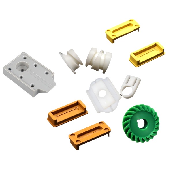
Plastic gear meshing with a metal shaft requires careful control of the bore fit and concentricity
When an “assorted CNC machined parts” order includes plastic gears (typically POM/acetal, nylon/PA6, or PEEK) that must mesh with a machined metal shaft or pinion, the critical interface is not the gear teeth (which are molded, not machined) but the gear’s bore and its relationship to the pitch circle. If the bore is eccentric to the pitch circle by more than 0.02 mm for a small gear (module 0.5–1.0), the gear will produce once-per-revolution variation in backlash and center distance—felt as “lumpiness” in the rotation even if the gear teeth themselves are perfectly formed.
We do not mold plastic gears; they are supplied by the customer or by a partner molder. Our role is to machine the mating metal component (shaft, pinion, or housing bore) to a tolerance that accommodates the plastic gear’s actual (not nominal) dimensions. This means we measure the customer-supplied sample gears’ bore diameter, pitch circle runout, and tooth thickness before final-machining our metal parts, then adjust our target dimensions based on those measurements rather than relying on the drawing’s nominal values. The adjustment is typically ±0.01–0.02 mm on the shaft diameter or housing bore—small enough to be within most drawing tolerances but large enough to compensate for typical molding variation.
Plastic clip engagement force depends on the machined undercut geometry it snaps into
A plastic clip—a retaining clip, a snap-fit cover, or a cable management clip—engages with a machined groove, ledge, or undercut on the metal part. The engagement force (the force required to snap the clip into place) and the retention force (the force required to remove it) are determined by the clip’s own design (which we don’t control) and by the geometry of the machined feature it engages with (which we do control).
The key parameters we control are: the undercut depth (how far the clip’s barb must deflect to clear the edge), the entry radius (whether there is a lead-in chamfer that reduces the initial deflection force), and the surface finish of the engagement surface (rough surfaces increase friction and make both insertion and removal harder). We machine undercuts with a T-slot cutter or a form tool to the depth specified on the customer’s clip drawing (or to 0.3–0.5 mm if unspecified, which works with most standard snap-clip designs). The entry edge gets a 0.2 × 45° chamfer unless a sharp edge is specifically required for retention. Surface finish in the undercut is Ra ≤ 1.6 µm (standard milling) or Ra ≤ 0.8 µm (light finishing pass) if the clip material is prone to abrasion wear during repeated installation/removal cycles.
Differential thermal expansion between plastic and metal must be accounted for in the assembly clearance
When a plastic gear or clip assembles onto a metal shaft or into a metal housing, the different coefficients of thermal expansion (CTE) mean that the fit at room temperature may not be the fit at operating temperature. A POM gear (CTE ≈ 100–120 µm/m·K) pressed onto a steel shaft (CTE ≈ 12 µm/m·K) will expand roughly 10× more than the shaft when temperature rises from 20 °C to 60 °C. For a 20 mm bore gear, this differential expansion is approximately 20 mm × (110–12) × 10⁻⁶ × 40 = 0.079 mm—enough to convert a light press-fit (0.01–0.02 mm interference) into a slip-fit at elevated temperature, potentially allowing the gear to shift or spin on the shaft under load.
We account for this by designing the metal shaft diameter at the high end of the press-fit tolerance band when the mating component is plastic and the operating temperature range exceeds 30 °C. Alternatively, we recommend the customer add a mechanical key or splined connection in addition to (or instead of) the press-fit, which eliminates reliance on friction alone for torque transmission across the full temperature range.
Machined features for plastic component integration must avoid stress concentrators in the plastic
Plastic parts are sensitive to stress concentrators—sharp corners, sudden section changes, and notches—that would be insignificant in a metal part but can initiate cracks in plastic under cyclic loading or impact. When we machine features that interface with plastic components (mounting bosses, alignment pins, snap-fit grooves), we apply generous radii (R0.5 mm minimum, R1–R2 mm preferred) at all internal corners and break all external edges to 0.2–0.3 mm chamfer or radius.
The cost of adding these radii is negligible (a single additional toolpath pass with a ballnose end mill or a deburring brush operation) but the benefit in terms of plastic-part durability is substantial. We have seen cases where a sharp internal corner (R0.1 mm, left by a standard end mill) caused a POM gear boss to crack after only 10⁴ thermal cycles—an early failure that was eliminated entirely by increasing the corner radius to R1 mm at essentially zero added cost.
How we handle mixed-material orders where CNC metal parts must mate with customer-supplied plastic components
“Assorted CNC machined parts with plastic gears and clips” orders always involve a mix of materials that we machine (metal) and materials that we don’t (plastic). Our process for handling these mixed orders:
- Request samples: Before starting production, we ask the customer to send us 3–5 samples of each plastic component (gear, clip, etc.) that will mate with our machined parts. These samples represent the actual molding output, not just the CAD model.
- Measure samples: We measure each sample’s critical interfacing dimensions (bore ID, pitch circle runout, clip engagement geometry, overall dimensions) and calculate the mean and range. This tells us what the plastic parts actually are, versus what the drawing says they should be.
- Adjust machining targets: Based on the measured sample data, we set our machining targets to the center of the combined tolerance zone (metal tolerance + plastic actual range). This maximizes the probability of successful first-time assembly for the customer.
- First-article assembly test: We assemble the first metal part with one of the customer’s plastic samples and verify: the gear meshes without binding, the clip snaps in/out with the expected force, and there is no interference or excessive clearance. Photos and measurements are sent to the customer for approval before we continue production.
- Ship metal parts with sample report: The shipment includes a one-page summary of the plastic sample measurements and how our metal parts were adjusted to match. This documentation helps the customer’s receiving inspection understand why some dimensions may differ slightly from the drawing nominal values.
This sample-based approach has reduced our mixed-material assembly escape rate from ~8 % (when we machined strictly to drawing nominals without seeing the actual plastic parts) to < 0.5 % (after implementing the sample-measure-adjust protocol).
CNC Machining Parts is the parent range for parts like this one; the overview page gathers the tooling logic, finishing options and tolerance notes that apply across the family.
Specifications
| Item | Assorted CNC Machined Parts with Plastic Gears and Clips |
|---|---|
| Brand | AUNOV |
| Designing | Share your print, or send a part to be measured, you get a DFM review together with the quotation. |
| Tooling | Every die designed and built in our toolroom, held under your part number. |
| Samples | Samples for approval come with dimensional data and material certification. |
| Materials | Carbon steel (SPCC / DC01), 304 / 316 stainless steel, aluminium, brass and copper are stocked, with the final grade confirmed at the drawing review. |
| Surface finish | Plating, e-coat, powder coating, anodising or passivation as the drawing calls out, per your print. |
| Processing | The draw sequence is staged, with in-line annealing wherever the draw ratio requires; piercing and CNC machining are done in house. |
| Equipment | Our press floor runs 5-250 T mechanical and 250-500 T hydraulic presses, in-house CNC cells and a temperature-controlled inspection room. |
| Tolerance | Expect +/-0.1 mm as drawn and +/-0.03 mm where surfaces are machined. |
| Delivery terms | FOB standard, DDP offered for EU and US, T/T and L/C; D/P on repeat accounts, call-off schedules and blanket orders supported. |
Related Products


Request a Quote for This Part
Send a drawing or sketch — get material advice, tooling cost and a per-piece price within 24 hours (working days).